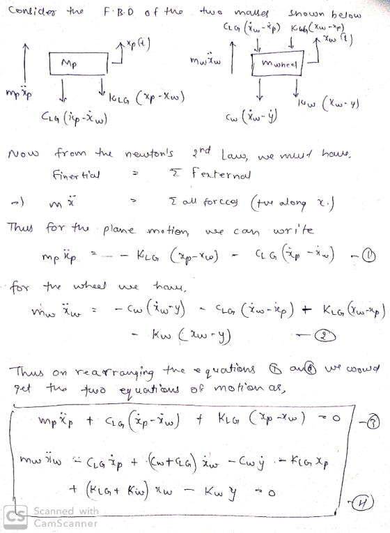
It is a question of studying the dynamic behavior of landing gear (LG) of a F18 landing. To simulate the behavior of the system we use the figure below.The term 'mwheel' denotes the total mass of the constituent members of the wheel. We want to know the displacement 'xplane(t)' of the mass 'mplane' for different scenarios. We consider that the state of the airstrips can be represented by an entry 'y(t)' which simulates the real geometry of the roadway. The tire is modeled by a linear wheel k and a shock absorber wheel c. You are asked to: 1. Establish the dynamic equations of system operation; 2. Model the detailed block diagram of the system; 3. Deduce the expression of the transfer function: H(s)= Xplane(s)/Y(s) , the initial conditions being assumed to be zero;
 The term 'mwheel' denotes the total mass of the constituent members of the wheel.
We want to know the displacement 'xplane(t)' of the mass 'mplane' for different scenarios.
We consider that the state of the airstrips can be represented by an entry 'y(t)' which simulates the
real geometry of the roadway. The tire is modeled by a linear wheel k and a shock absorber
wheel c.
You are asked to:
1. Establish the dynamic equations of system operation;
2. Model the detailed block diagram of the system;
3. Deduce the expression of the transfer function: H(s)= Xplane(s)/Y(s) , the initial conditions
being assumed to be zero;
The term 'mwheel' denotes the total mass of the constituent members of the wheel.
We want to know the displacement 'xplane(t)' of the mass 'mplane' for different scenarios.
We consider that the state of the airstrips can be represented by an entry 'y(t)' which simulates the
real geometry of the roadway. The tire is modeled by a linear wheel k and a shock absorber
wheel c.
You are asked to:
1. Establish the dynamic equations of system operation;
2. Model the detailed block diagram of the system;
3. Deduce the expression of the transfer function: H(s)= Xplane(s)/Y(s) , the initial conditions
being assumed to be zero;
Homework Answers
In this solution some basic concepts and formulas of Vibration Mechanics are used. For more information, refer to any standard textbook or drop a comment below. Please give a Thumbs Up, if solution is helpful.
Solution :


NOTE : Feel free to ask further queries. Your positive rating would be appreciated and motivate me !
Add Answer to:
It is a question of studying the dynamic behavior of landing gear (LG) of a F18 landing. To simulate the behavior of the...
Qu (4) A simplified landing gear system on airplane shown comprises of masses, springs and viscous...
 Qu (4) A simplified landing gear system on airplane shown comprises of masses, springs and viscous dampers. Assuming the system can be modeled as a 2nd order system described as RUNNION AXLE TRUNNION BEAM 6 AUKILIARY SHocK ABSORBER 2 MAIN SHOCK ABSORBER ! DRAG/STDE STRUTss WHEEL AXLE PRIMARY STS SLIDING PISTON ORALTERNATE MID WHEEL AXLE 3 dy+12+100y 450u dt /o dt TRUCK BEAM MID WHEEL AXLE4 (a) Determine the system TF (b) Determine the system poles and WHEEL AXLE and...
.matlab Objective: This activity has the purpose of helping students to to use either Simulink or VisSim to simulate the system behavior based on its Block Diagram representation and plot its resp...
 .matlab
Objective: This activity has the purpose of helping students to to use either Simulink or VisSim to simulate the system behavior based on its Block Diagram representation and plot its response. Student Instructions: The following spring-mass-damper system has no external forcing, that is u(0)-0. At time t- 0 it has an initial condition for the spring, which it is distended by one unit: y(0)-1. The system will respond to this initial condition (zero-input-response) until it reaches equilibrium. 0)1initial condition...
.matlab
Objective: This activity has the purpose of helping students to to use either Simulink or VisSim to simulate the system behavior based on its Block Diagram representation and plot its response. Student Instructions: The following spring-mass-damper system has no external forcing, that is u(0)-0. At time t- 0 it has an initial condition for the spring, which it is distended by one unit: y(0)-1. The system will respond to this initial condition (zero-input-response) until it reaches equilibrium. 0)1initial condition...
Objective: This activity has the purpose of helping students to to use either Simulink or VisSim to simulate the system behavior based on its Block Diagram representation and plot its response...
 Objective: This activity has the purpose of helping students to to use either Simulink or VisSim to simulate the system behavior based on its Block Diagram representation and plot its response Student Instructions: The following spring-mass-damper system has no external forcing, that is Lu(0) 0. At time t"0 it has an initial condition for the spring, which it is distended by one unit; yO) 1. The system will respond to this initial condition (zero-input-response) until it reaches equilibriunm. | yin«...
An engineering company is designing and testing a car suspension system. The system has a convent...
An engineering company is designing and testing a car suspension system. The system has a conventional suspension design, consisting of a shock-absorber and spring at each wheel. The shock-absorber provides a damping effect that is proportional to the vertical speed (i.e. up and down motion) of the wheel, and the spring's resistance is proportional to the vertical displacement of the wheel. The design team analyses the suspension system in two separate parts: Part 1 - dynamics of the spring-damper system;...
 Qu (4) A simplified landing gear system on airplane shown comprises of masses, springs and viscous dampers. Assuming the system can be modeled as a 2nd order system described as RUNNION AXLE TRUNNION BEAM 6 AUKILIARY SHocK ABSORBER 2 MAIN SHOCK ABSORBER ! DRAG/STDE STRUTss WHEEL AXLE PRIMARY STS SLIDING PISTON ORALTERNATE MID WHEEL AXLE 3 dy+12+100y 450u dt /o dt TRUCK BEAM MID WHEEL AXLE4 (a) Determine the system TF (b) Determine the system poles and WHEEL AXLE and...
 .matlab
Objective: This activity has the purpose of helping students to to use either Simulink or VisSim to simulate the system behavior based on its Block Diagram representation and plot its response. Student Instructions: The following spring-mass-damper system has no external forcing, that is u(0)-0. At time t- 0 it has an initial condition for the spring, which it is distended by one unit: y(0)-1. The system will respond to this initial condition (zero-input-response) until it reaches equilibrium. 0)1initial condition...
.matlab
Objective: This activity has the purpose of helping students to to use either Simulink or VisSim to simulate the system behavior based on its Block Diagram representation and plot its response. Student Instructions: The following spring-mass-damper system has no external forcing, that is u(0)-0. At time t- 0 it has an initial condition for the spring, which it is distended by one unit: y(0)-1. The system will respond to this initial condition (zero-input-response) until it reaches equilibrium. 0)1initial condition...
 Objective: This activity has the purpose of helping students to to use either Simulink or VisSim to simulate the system behavior based on its Block Diagram representation and plot its response Student Instructions: The following spring-mass-damper system has no external forcing, that is Lu(0) 0. At time t"0 it has an initial condition for the spring, which it is distended by one unit; yO) 1. The system will respond to this initial condition (zero-input-response) until it reaches equilibriunm. | yin«...
Most questions answered within 3 hours.
-
What is the % w/v when 80 mL of a 2.0% solution is mixed with 50...
asked 3 minutes ago -
How can I solve the following using a TI83
Claim: Most adults would erase all of...
asked 15 minutes ago -
Analysis of 3-ethyl-3-buten-2-ol gave C, 72.13%; H, 11.92%.
Calculate the percent deviation of these results from...
asked 12 minutes ago -
Which VALS segment is most likely to have a top of the line
brand new (2015)...
asked 16 minutes ago -
Write a program to score the paper-rock-scissor game. Each of
two users types in either P,R...
asked 37 minutes ago -
Calculate the equillibrium constent K for a redox reaction that
has E°cell = -.98 V at...
asked 49 minutes ago -
A concave spherical mirror has a radius of curvature of
magnitude 19.6 cm.
(a) Find the...
asked 50 minutes ago -
3. draw a diagram of the magnetic field:
a. around a long straight wire with a...
asked 49 minutes ago -
If you titrated 30.0 mL of 0.1 M HCl with 0.1 M NaOH, indicate
the approximate...
asked 57 minutes ago -
NADH passes electrons into the electron transport chain. List
the carriers that would receive the electrons,...
asked 1 hour ago -
A cylindrical cable with a resistivity of 1.6x10⁻⁸ Ω·m and cross
sectional area of 3x10⁻⁵ m^2...
asked 1 hour ago -
True or False.
A consumer with convex preferences who is indifferent between
the bundles (5,2) and...
asked 1 hour ago