
Homework Answers


Add Answer to:
2. (70pt) For the system shown below: w bending moment (M) and shear force diagrams (V) using Moment Distribution (...
For the beam shown in Fig. 9.3, draw the shear force and bending moment diagrams. Use...
 For the beam shown in Fig. 9.3, draw the shear force and bending moment diagrams. Use the area method that relies on the relationships between loading and shear force and between shear force and bending moment. Indicate the slope of the shear force diagram at locations A, B, C, and D using the load information in Fig. 9.3. Indicate the slope of the bending moment diagram at the same four locations using information from the shear force diagram. | 6...
draw axial force, shear force and bending moment diagrams 2m 4'm 30 kN 2m 50 kN...
 draw axial force, shear force and bending moment
diagrams
2m 4'm 30 kN 2m 50 kN 4m A 3 m 1m -3m 1.5m
draw axial force, shear force and bending moment
diagrams
2m 4'm 30 kN 2m 50 kN 4m A 3 m 1m -3m 1.5m
4. For the beam and loading shown, draw the shear force and bending moment diagrams and...
 4. For the beam and loading shown, draw the shear force and bending moment diagrams and determine the maximum bending and shear force and their locations. 20 KN 40 KN B D 250 mm |--2.5 m- 3m-4-2 m 80 mm 5. For the beam and loading shown, draw the shear force and bending moment diagrams and determine the maximum bending and shear force and their locations. 50 KN
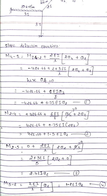
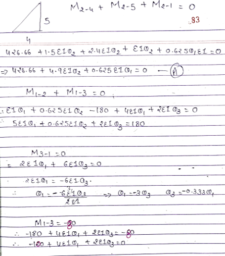
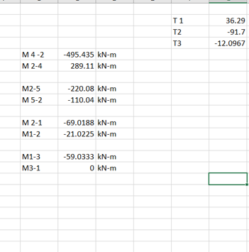
Use the Slope-Deflection Method to analyse the structure of Figure 1 and draw the shear force, axial force, and bending moment diagrams 4 m (1.5 EI) 20 KN/m 10 KN/m 50 kN.m Figure 1 Use the Slop...
 Use the Slope-Deflection Method to analyse the structure of Figure 1 and draw the shear force, axial force, and bending moment diagrams 4 m (1.5 EI) 20 KN/m 10 KN/m 50 kN.m Figure 1
Use the Slope-Deflection Method to analyse the structure of Figure 1 and draw the shear force, axial force, and bending moment diagrams 4 m (1.5 EI) 20 KN/m 10 KN/m 50 kN.m Figure 1
Use the Slope-Deflection Method to analyse the structure of Figure 1 and draw the shear force, axial force, and bending moment diagrams 4 m (1.5 EI) 20 KN/m 10 KN/m 50 kN.m Figure 1
Use the graphical method to construct the shear-force and bending-moment diagrams for the beam shown.
 Use the graphical method to construct the shear-force and bending-moment diagrams for the beam shown. Label all significant points on each diagram and identify the maximum moments along with their respective locations. For all answers entered, use the sign convention for shear forces and bending moments. (a) Find the location x and the corresponding bending moment M at the one point between A and B at which the shear force equals zero. (b) Consider the entire beam and determine the maximum positive...
Use the graphical method to construct the shear-force and bending-moment diagrams for the beam shown. Label...
 Use the graphical method to construct the shear-force and bending-moment diagrams for the beam shown. Label all significant points on each diagram and identify the maximum moments along with their respective locations. For all answers entered, use the sign convention for shear forces and bending moments (a) Find the location x and the corresponding bending moment M at the one point between A and D at which the shear force equals zero. (b) Consider the entire beam and determine the...
#1) (65p.) Draw the Shear Force (V) and Bending Moment (M) diagrams of statically indeterminate beam...
 #1) (65p.) Draw the Shear Force (V) and Bending Moment (M) diagrams of statically indeterminate beam shown in figure using “Force Method”. The (roller) support at “B” settles 35 mm. The moment of inertia is given by (1) for regions “AB”, “BC” and “CD”; however it is equal to (21) for the region “DE”. (“B” is the roller and “E” is the fixed type of support). [The flexural rigidity: EI=40000 kNm?] 60 kN 10 kN/m 1 A B X (1)...
Draw the Shear Force (V) and Bending Moment (MI) diagrams of statically indeterminate beam shown in...
 Draw the Shear Force (V) and Bending Moment (MI) diagrams of statically indeterminate beam shown in figure using “Force Method”. The (roller) support at "B" settles 35 mm. The moment of inertia is given by (1) for regions "AB", "BC" and "CD"; however it is equal to (21) for the region “DE”. ("B" is the roller and “E" is the fixed type of support). [The flexural rigidity: EI=40000 kNm] 60 KN y 10 kN/m A - Tu (21) 1.5m 11...
48 KN/m 1- Shear Force Diagram: с 72 KN 2m 4m 2m 54 KN D 8m...
 48 KN/m 1- Shear Force Diagram: с 72 KN 2m 4m 2m 54 KN D 8m D 4m 4m B B Steps of Calculation: 5m 5m 2- Moment Diagram: a) Draw the V and M diagrams of the three-hinged-frame. b) Calculate the value of the horizontal displacement of C point. EI: Constant D a) Determination The Values of The Reaction Force: B Steps of Calculation: b) Calculation The Value of Displacement: Belge sonu
#1) (65p.) Draw the Shear Force (V) and Bending Moment (M) diagrams of statically indeterminate beam...
 #1) (65p.) Draw the Shear Force (V) and Bending Moment (M) diagrams of statically indeterminate beam shown in figure using "Force Method". The (roller) support at "B" settles 35 mm. The moment of inertia is given by (1) for regions "AB", "BC" and "CD": however it is equal to (21) for the region "DE". ("B" is the roller and "E" is the fixed type of support). [The flexural rigidity: EI-40000 kNm] 60 KN 10 kN/m B L (21) 1.5 X...
 For the beam shown in Fig. 9.3, draw the shear force and bending moment diagrams. Use the area method that relies on the relationships between loading and shear force and between shear force and bending moment. Indicate the slope of the shear force diagram at locations A, B, C, and D using the load information in Fig. 9.3. Indicate the slope of the bending moment diagram at the same four locations using information from the shear force diagram. | 6...
 draw axial force, shear force and bending moment
diagrams
2m 4'm 30 kN 2m 50 kN 4m A 3 m 1m -3m 1.5m
draw axial force, shear force and bending moment
diagrams
2m 4'm 30 kN 2m 50 kN 4m A 3 m 1m -3m 1.5m
 4. For the beam and loading shown, draw the shear force and bending moment diagrams and determine the maximum bending and shear force and their locations. 20 KN 40 KN B D 250 mm |--2.5 m- 3m-4-2 m 80 mm 5. For the beam and loading shown, draw the shear force and bending moment diagrams and determine the maximum bending and shear force and their locations. 50 KN
 Use the Slope-Deflection Method to analyse the structure of Figure 1 and draw the shear force, axial force, and bending moment diagrams 4 m (1.5 EI) 20 KN/m 10 KN/m 50 kN.m Figure 1
Use the Slope-Deflection Method to analyse the structure of Figure 1 and draw the shear force, axial force, and bending moment diagrams 4 m (1.5 EI) 20 KN/m 10 KN/m 50 kN.m Figure 1
Use the Slope-Deflection Method to analyse the structure of Figure 1 and draw the shear force, axial force, and bending moment diagrams 4 m (1.5 EI) 20 KN/m 10 KN/m 50 kN.m Figure 1
 Use the graphical method to construct the shear-force and bending-moment diagrams for the beam shown. Label all significant points on each diagram and identify the maximum moments along with their respective locations. For all answers entered, use the sign convention for shear forces and bending moments. (a) Find the location x and the corresponding bending moment M at the one point between A and B at which the shear force equals zero. (b) Consider the entire beam and determine the maximum positive...
 Use the graphical method to construct the shear-force and bending-moment diagrams for the beam shown. Label all significant points on each diagram and identify the maximum moments along with their respective locations. For all answers entered, use the sign convention for shear forces and bending moments (a) Find the location x and the corresponding bending moment M at the one point between A and D at which the shear force equals zero. (b) Consider the entire beam and determine the...
 #1) (65p.) Draw the Shear Force (V) and Bending Moment (M) diagrams of statically indeterminate beam shown in figure using “Force Method”. The (roller) support at “B” settles 35 mm. The moment of inertia is given by (1) for regions “AB”, “BC” and “CD”; however it is equal to (21) for the region “DE”. (“B” is the roller and “E” is the fixed type of support). [The flexural rigidity: EI=40000 kNm?] 60 kN 10 kN/m 1 A B X (1)...
 Draw the Shear Force (V) and Bending Moment (MI) diagrams of statically indeterminate beam shown in figure using “Force Method”. The (roller) support at "B" settles 35 mm. The moment of inertia is given by (1) for regions "AB", "BC" and "CD"; however it is equal to (21) for the region “DE”. ("B" is the roller and “E" is the fixed type of support). [The flexural rigidity: EI=40000 kNm] 60 KN y 10 kN/m A - Tu (21) 1.5m 11...
 48 KN/m 1- Shear Force Diagram: с 72 KN 2m 4m 2m 54 KN D 8m D 4m 4m B B Steps of Calculation: 5m 5m 2- Moment Diagram: a) Draw the V and M diagrams of the three-hinged-frame. b) Calculate the value of the horizontal displacement of C point. EI: Constant D a) Determination The Values of The Reaction Force: B Steps of Calculation: b) Calculation The Value of Displacement: Belge sonu
 #1) (65p.) Draw the Shear Force (V) and Bending Moment (M) diagrams of statically indeterminate beam shown in figure using "Force Method". The (roller) support at "B" settles 35 mm. The moment of inertia is given by (1) for regions "AB", "BC" and "CD": however it is equal to (21) for the region "DE". ("B" is the roller and "E" is the fixed type of support). [The flexural rigidity: EI-40000 kNm] 60 KN 10 kN/m B L (21) 1.5 X...
Most questions answered within 3 hours.
-
describe in detail your "perfect" place to study in your home
giving great detail to how...
asked 11 minutes ago -
Decide with a brief explanation of the following statements
about reaction rates and catalysis are true:...
asked 13 minutes ago -
Write a grading program in Java for a class with the following
grading policies: There are...
asked 15 minutes ago -
Can someone explain the process of this Display a text
file program and show the supposed...
asked 27 minutes ago -
When a solid dissolves in water, heat may be evolved or
absorbed. The heat of dissolution...
asked 30 minutes ago -
Leechtown Co. has 4.3 percent coupon bonds on the market with 18
years left to maturity....
asked 32 minutes ago -
Comment on how the conference could have been improved What
additional elements would you consider adding...
asked 41 minutes ago -
Sandra Clothing Company has invested $51,000,000 in its
business. The target rate of return for the...
asked 42 minutes ago -
"Discover the privacy concerns when applying Artificial
Intelligence into Big Data"
asked 42 minutes ago -
Explain why organisms that can survive and/or grow under aerobic
conditions need the enzymes catalase and...
asked 48 minutes ago -
Moonwalker Corporation issued 2,000 shares of its $10 par value
common stock for $60,000. Moonwalker also...
asked 47 minutes ago -
A microphone connected to an amplifier takes a 10 dB voice and
turns it into a...
asked 52 minutes ago