
Homework Answers
a)
b)
Stress = F/A = 
Youngs Modulus = Stress/Strain
Strain , 

Gauge Factor = 


Add Answer to:
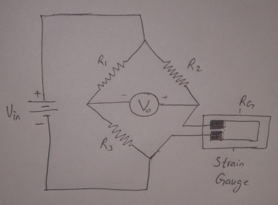
Question 2 Figure Q2 shows a strain gauge bonded to a piece of steel under a...
A 120 ? strain gauge with a gauge factor of 2 is mounted on a beam...
 A 120 Ω strain gauge with a gauge factor of 2 is mounted on a beam and connected in a Wheatstone bridge as shown in Figure Q1a. The bridge is powered by a 12 V DC supply in series with a 510 Ω resistance. The beam is subject to a tensile force, which produces an axial strain of 940 microstrain measured by the strain gauge .a) Under no strain, calculate the current in the strain gauge and the power dissipated by the...
2) One arm of a Wheatstone bridge is a 50 k2 strain gauge (S = 2.0)....
 2) One arm of a Wheatstone bridge is a 50 k2 strain gauge (S = 2.0). This strain gauge is bonded to a metal fixture for tensile loading, and the metal has a Young's Modulus E-2.5 MPa. The other 3 arms are fixed 50 kO resistors. The bridge is powered by 5Vv DC as shown, and Eo is the output voltage. a) Derive a relationship for Eo as a function of tensile stress o in the metal substrate, ΔL ....
Question 2 I (a) Using a 459 strain gauge rosette placed on a mild steel structure,...
 Question 2 I (a) Using a 459 strain gauge rosette placed on a mild steel structure, the following strains were established from the measurements taken:£x = 75x10", Eyy =-115x10-6 = 210 10-6 and Yxy yy (i) Determine the corresponding normal stresses Ox and and shear stress txy. For mild steel, use Young's modulus E= 205 GPa , Poisson's ratio v=0.3 and shear modulus G = 78.8 GPa. [6 marks] (ii) Using the values obtained in (i), determine the principal stresses...
3. Two different types of strain gauges with a nominal resistance of 120 2 are both...
 3. Two different types of strain gauges with a nominal resistance of 120 2 are both used to measure an axial strain in Figure 3. They are connected to a Wheatstone bridge (the lead wire effect is negligible) at R1 and R3 R3 is a nickel wire strain gauge with a gauge factor -12.1 and R1 is a nicrome wire strain gauge with a gauge factor 2.1. The bridge has a supply voltage of 4.5V and two fixed resistors R2...
Asap 1. The bracket is made of steel (Young's modulus 200 GPa; Poisson's ratio 0.3). When the force P is applied to the bracket, the gages in the strain rosette at point A have the followi...
 Asap
1. The bracket is made of steel (Young's modulus 200 GPa; Poisson's ratio 0.3). When the force P is applied to the bracket, the gages in the strain rosette at point A have the following readings: E.-60 μ . Ep 135 μ l, and E.-264 μ (a) Determine the shear strain at point A. (b) Determine the orientation of the principal plane, the in-plane principal strains, the maximum in-plane shear strain, and the average in-plane normal strain. Determine the...
Asap
1. The bracket is made of steel (Young's modulus 200 GPa; Poisson's ratio 0.3). When the force P is applied to the bracket, the gages in the strain rosette at point A have the following readings: E.-60 μ . Ep 135 μ l, and E.-264 μ (a) Determine the shear strain at point A. (b) Determine the orientation of the principal plane, the in-plane principal strains, the maximum in-plane shear strain, and the average in-plane normal strain. Determine the...
5. (20 points) We use strain gauge to create a fish weight scale. The strain gauges are mounted on a plastic tube with fish hanging on to it. The strain gauges have resistance R 2400 2 (unstrained...
 5. (20 points) We use strain gauge to create a fish weight scale. The strain gauges are mounted on a plastic tube with fish hanging on to it. The strain gauges have resistance R 2400 2 (unstrained) and the GF 2.14. A (1) Which is the dummy gauge, A or B? Circle the dummy gauge. (2) Show how to wire the two gauges and two fixed 2400 Ω resistors into the bridge circuit to provide temperature compensation, using the graphs...
Question #2 [12 marks] 15 mm The Figure shows a steel bar of rectangular cross section...
 Question #2 [12 marks] 15 mm The Figure shows a steel bar of rectangular cross section (10x40 mm) carries a tensile load P and is attached to a support by means of a round pin of diameter 15 mm. The allowable stresses for the bar in tension and the pin in shear are Gallow -120 MPa and Tallow 60 MPa, respectively. What is the maximum permissible value of 10 mm the load P? 40 mm Question #3 [16 marks] Cross...
Draw a schematic stress-strain diagram for steel. Make sure you mark all the important points and regions on it
 1. Draw a schematic stress-strain diagram for steel. Make sure you mark all the important points and regions on it. Provide a one-two sentence explanation for each point and region along the diagram. 2. A cylindrical specimen of a nickel alloy having an elastic modulus of 207 GPa (30 x 10* psi) and an original diameter of 10.2 mm (0.40 In.) will experience only elastic deformation when a tensile load of 8900 N (2000 Ibe) is applied. Compute the maximum length...
Answers: QUESTION 3 (TZU marks) subjected an internal gauge modulus of elasticity of 210 GPa and...
 Answers:
QUESTION 3 (TZU marks) subjected an internal gauge modulus of elasticity of 210 GPa and a A closed cylindrical pressure vessel illustrated in the figure below is pressure of 5.0 MPa. The vessel is made of steel with a Poisson's ratio of 0.29. A delta strain gauge rosette, attached to the external surface of a closed cylindrical pressure vessel measures the following strains a 74 x 10-6 10-6 E60 246 x 248 x 10 E120 Determine the strain components...
Answers:
QUESTION 3 (TZU marks) subjected an internal gauge modulus of elasticity of 210 GPa and a A closed cylindrical pressure vessel illustrated in the figure below is pressure of 5.0 MPa. The vessel is made of steel with a Poisson's ratio of 0.29. A delta strain gauge rosette, attached to the external surface of a closed cylindrical pressure vessel measures the following strains a 74 x 10-6 10-6 E60 246 x 248 x 10 E120 Determine the strain components...
An existing steel beam is in use in a building.
 An existing steel beam is in use in a building. Using a rectangular strain gauge rosette, the actual strains at point A have been recorded while being subjected to test loads which simulate crowd loading. It is necessary to calculate the principal stresses to check whether the beam is safe for its current purpose (ie: assess whether the stresses determined are less than the maximum permissible stresses) Figure 4: Strain gauge rosette location and recorded strains In this case it is reasonable...
 A 120 Ω strain gauge with a gauge factor of 2 is mounted on a beam and connected in a Wheatstone bridge as shown in Figure Q1a. The bridge is powered by a 12 V DC supply in series with a 510 Ω resistance. The beam is subject to a tensile force, which produces an axial strain of 940 microstrain measured by the strain gauge .a) Under no strain, calculate the current in the strain gauge and the power dissipated by the...
 2) One arm of a Wheatstone bridge is a 50 k2 strain gauge (S = 2.0). This strain gauge is bonded to a metal fixture for tensile loading, and the metal has a Young's Modulus E-2.5 MPa. The other 3 arms are fixed 50 kO resistors. The bridge is powered by 5Vv DC as shown, and Eo is the output voltage. a) Derive a relationship for Eo as a function of tensile stress o in the metal substrate, ΔL ....
 Question 2 I (a) Using a 459 strain gauge rosette placed on a mild steel structure, the following strains were established from the measurements taken:£x = 75x10", Eyy =-115x10-6 = 210 10-6 and Yxy yy (i) Determine the corresponding normal stresses Ox and and shear stress txy. For mild steel, use Young's modulus E= 205 GPa , Poisson's ratio v=0.3 and shear modulus G = 78.8 GPa. [6 marks] (ii) Using the values obtained in (i), determine the principal stresses...
 3. Two different types of strain gauges with a nominal resistance of 120 2 are both used to measure an axial strain in Figure 3. They are connected to a Wheatstone bridge (the lead wire effect is negligible) at R1 and R3 R3 is a nickel wire strain gauge with a gauge factor -12.1 and R1 is a nicrome wire strain gauge with a gauge factor 2.1. The bridge has a supply voltage of 4.5V and two fixed resistors R2...
 Asap
1. The bracket is made of steel (Young's modulus 200 GPa; Poisson's ratio 0.3). When the force P is applied to the bracket, the gages in the strain rosette at point A have the following readings: E.-60 μ . Ep 135 μ l, and E.-264 μ (a) Determine the shear strain at point A. (b) Determine the orientation of the principal plane, the in-plane principal strains, the maximum in-plane shear strain, and the average in-plane normal strain. Determine the...
Asap
1. The bracket is made of steel (Young's modulus 200 GPa; Poisson's ratio 0.3). When the force P is applied to the bracket, the gages in the strain rosette at point A have the following readings: E.-60 μ . Ep 135 μ l, and E.-264 μ (a) Determine the shear strain at point A. (b) Determine the orientation of the principal plane, the in-plane principal strains, the maximum in-plane shear strain, and the average in-plane normal strain. Determine the...
 5. (20 points) We use strain gauge to create a fish weight scale. The strain gauges are mounted on a plastic tube with fish hanging on to it. The strain gauges have resistance R 2400 2 (unstrained) and the GF 2.14. A (1) Which is the dummy gauge, A or B? Circle the dummy gauge. (2) Show how to wire the two gauges and two fixed 2400 Ω resistors into the bridge circuit to provide temperature compensation, using the graphs...
 Question #2 [12 marks] 15 mm The Figure shows a steel bar of rectangular cross section (10x40 mm) carries a tensile load P and is attached to a support by means of a round pin of diameter 15 mm. The allowable stresses for the bar in tension and the pin in shear are Gallow -120 MPa and Tallow 60 MPa, respectively. What is the maximum permissible value of 10 mm the load P? 40 mm Question #3 [16 marks] Cross...
 Answers:
QUESTION 3 (TZU marks) subjected an internal gauge modulus of elasticity of 210 GPa and a A closed cylindrical pressure vessel illustrated in the figure below is pressure of 5.0 MPa. The vessel is made of steel with a Poisson's ratio of 0.29. A delta strain gauge rosette, attached to the external surface of a closed cylindrical pressure vessel measures the following strains a 74 x 10-6 10-6 E60 246 x 248 x 10 E120 Determine the strain components...
Answers:
QUESTION 3 (TZU marks) subjected an internal gauge modulus of elasticity of 210 GPa and a A closed cylindrical pressure vessel illustrated in the figure below is pressure of 5.0 MPa. The vessel is made of steel with a Poisson's ratio of 0.29. A delta strain gauge rosette, attached to the external surface of a closed cylindrical pressure vessel measures the following strains a 74 x 10-6 10-6 E60 246 x 248 x 10 E120 Determine the strain components...
Most questions answered within 3 hours.
-
What mechanisms Drive speciation??
(I.e. what was Dawins theory on the orgin of species, and how...
asked 1 hour ago -
The manager at a car assembly plant believes that the mean
assembly time for a car...
asked 2 hours ago -
Which of the following is true of electron capture?
A) It decreases the nuclide's mass number...
asked 3 hours ago -
Assuming an efficiency of 43.10%, calculate the actual yield of
magnesium nitrate formed from 114.9 g...
asked 4 hours ago -
The highly pathogenic bacterium Clostridium
perfringens causes gangrene, a disease that results in the
destruction of...
asked 5 hours ago -
In the context of situation analysis, which of the following is
a category for analysis in...
asked 5 hours ago -
In a study of the gas phase decomposition of sulfuryl chloride
at 600 K SO2Cl2(g)SO2(g) +...
asked 5 hours ago -
75 g of 2-propanol (C3H8O) and 25 g of pentane are mixed in a
200 mL...
asked 5 hours ago -
The 2800-turn coil in a dc motor has an area per turn of 1.1 ×
10-2...
asked 6 hours ago -
Draw a combinational logic circuit diagram with a symbol inside
the box for two I/P of...
asked 6 hours ago -
The cliché we use quite a lot in finance is: there is a need to
maximize...
asked 6 hours ago -
In class we discussed the addition of HCl to alpha pinene. Would
you expect one or...
asked 6 hours ago