

SACRAMENTO STATE Department of Cvil Engineering Quiz 2 Additional Problems Name For all problems below: (NO CALCULATIONS) Show where you would make the necessary cuts on the figure below to describe the deflected shape of the beam using the double integration method and CLEARLY label your axes on the figure? (4 points) Draw the free body diagrams that you would analyze given your cuts (DO NOT NEED TO WRITE EQUILIBRIUM EQUATIONS). (4 points) List the boundary conditions needed to solve for constants of integration assuming you have ECHASTAINE
Homework Answers
The beam AC is supported by a smooth pin at A and a roller at B...
 The beam AC is supported by a smooth pin at A and a roller at B
as shown in the figure below.
a. Sketch the free-body diagram of the beam and use it to
determine the support reaction components at A and B.
b. Draw the shear and moment diagrams for the beam.
6. The beam AC is supported by a smooth pin at A and a roller at B as shown in the figure below. 6 kN 12 kN/m...
The beam AC is supported by a smooth pin at A and a roller at B
as shown in the figure below.
a. Sketch the free-body diagram of the beam and use it to
determine the support reaction components at A and B.
b. Draw the shear and moment diagrams for the beam.
6. The beam AC is supported by a smooth pin at A and a roller at B as shown in the figure below. 6 kN 12 kN/m...
3 ft, 3 ft 3 ft Problem 3. The beam is supported by a pin at...
 3 ft, 3 ft 3 ft Problem 3. The beam is supported by a pin at point B and a roller at point E. A distributed load q = 1 kip/ft is applied across AC, and a point load P = 5 kips and counter-clockwise moment M = 9 kips . ft are applied at point D. Determine the reactions at the supports, and draw the shear and bending moment diagrams.
Problem 3: The statically indeterminate propped cantilever beam is supported by a roller at A and...
 Problem 3: The statically indeterminate propped cantilever beam is supported by a roller at A and is fixed at B. The beam is subject a uniformly distributed load and concentrated moment as shown. E is 29000 ksi and 1 is 400 in Determine the equation of the moment as a function of x. b) a) Determine the equations of the beam slope and deflection as a functions ofx (do not substitute the values of E and I c) Find slope...
CE 160 Problem 1(15% 4 k B 12 ft AR 24 ft The statically determinate rigidly connected frame has a pin support at point A and a roller support at point C. The frame is subjected to a point load a...
 CE 160 Problem 1(15% 4 k B 12 ft AR 24 ft The statically determinate rigidly connected frame has a pin support at point A and a roller support at point C. The frame is subjected to a point load at point B. The frame is rigidly con- nected at point B. If the bending stiffness of column AB is 40,000 k-ft and the bending stiffness for beam BC is 60,000 k-ft, find: I. (596) The bending moment diagram for...
4 k B Elpc 12 ft ElAB 24 ft The statically determinate rigidly connected frame has a pin support at point A and a roller support at point C. The frame is subjected to a point load at point B. The...
 4 k B Elpc 12 ft ElAB 24 ft The statically determinate rigidly connected frame has a pin support at point A and a roller support at point C. The frame is subjected to a point load at point B. The frame is rigidly con- nected at point B. If the bending stiffness of column AB is 40,000 k-ft? and the bending stiffness for beam BC is 60,000 k-ft, find: 1. (5%) The bending moment diagram for the frame. Show...
problem 4 Use the double integration method to solve the following four problems. In each problem...
 problem 4
Use the double integration method to solve the following four problems. In each problem you should set x = 0 at the left end of the beam, with x increasing to the right. 4. The 18 ft long overhanging timber beam shown below is supported by Pin A and Roller B. The beam supports a downward point load of 1.5 kip at the right end (Point C) and a linearly varying (triangular) distributed load that varies from 0...
problem 4
Use the double integration method to solve the following four problems. In each problem you should set x = 0 at the left end of the beam, with x increasing to the right. 4. The 18 ft long overhanging timber beam shown below is supported by Pin A and Roller B. The beam supports a downward point load of 1.5 kip at the right end (Point C) and a linearly varying (triangular) distributed load that varies from 0...
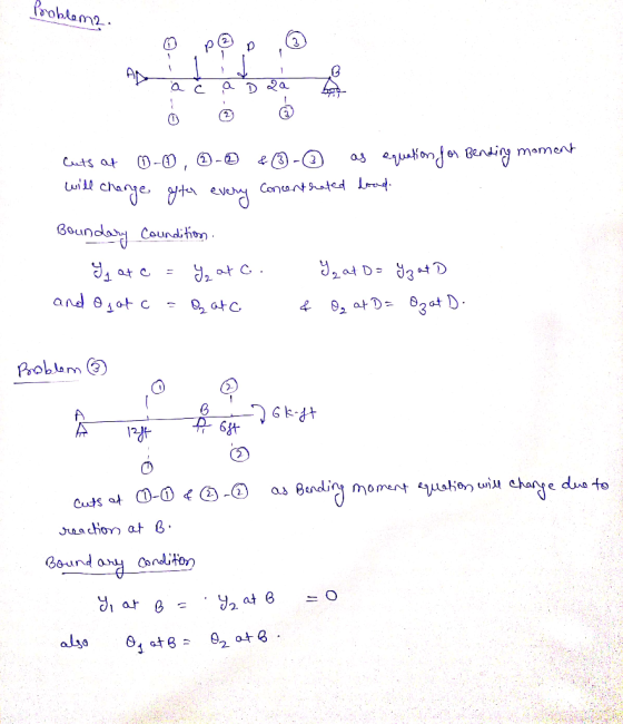
2.- The beam shown in the figure, has a roller support at A, a fixed support at C and an internal hinge at B. The lengths of segments AB and BC are and b respectively. A uniformly distributed load, q...
 2.- The beam shown in the figure, has a roller support at A, a fixed support at C and an internal hinge at B. The lengths of segments AB and BC are and b respectively. A uniformly distributed load, q, is applied between points B and C, and a concentrated load P acts at a distance 2a/3 from the support A. El is constant. (a) Determine the deflection o at the hinge using superposition. Clearly state the continuity conditions at...
QUESTION 2 Beam ABCD is 8 m in length and is pin-supported at A and roller-supported...
 QUESTION 2 Beam ABCD is 8 m in length and is pin-supported at A and roller-supported at C as shown in Figure Q2. A counter-clockwise concentrated moment acts about the support A. A uniformly-distributed load acts on span BC and a vertical concentrated load acts at the free end D a) Determine the reactions at supports A and C. 4 marks) b) Obtain the shear force and the bending moment functions (in terms of x) for each segment along the...
Blem 2. (70 points) 1. For the beam shown in Figure (a): a) b) draw the shear force and bending m...
 blem 2. (70 points) 1. For the beam shown in Figure (a): a) b) draw the shear force and bending moment diagrams. (30 points) Select the most economical W shape for the beam with an allowable bending stress of 30 ksi. (10 points) determine the maximum tensile and compressive bending stresses at any location along the beam if the section shown in Figure (b) is used instead of the W shape section selectedin Part b. Would the beam be safe...
The beam has the rectangular cross section shown. A beam of length 6 meters pin-supported 2...
 The beam has the rectangular cross section shown. A beam of
length 6 meters pin-supported 2 meters from the left end and
roller-supported 2 meters from the right end. The beam has a
rectangular cross section with base length 50 millimeters and
height 150 millimeters. Load: w, uniform along beam.
Part A If w = 4 kN/m , determine the maximum bending stress in
the beam.
Can you please draw out the moment and shear diagrams for this
one using...
The beam has the rectangular cross section shown. A beam of
length 6 meters pin-supported 2 meters from the left end and
roller-supported 2 meters from the right end. The beam has a
rectangular cross section with base length 50 millimeters and
height 150 millimeters. Load: w, uniform along beam.
Part A If w = 4 kN/m , determine the maximum bending stress in
the beam.
Can you please draw out the moment and shear diagrams for this
one using...
 The beam AC is supported by a smooth pin at A and a roller at B
as shown in the figure below.
a. Sketch the free-body diagram of the beam and use it to
determine the support reaction components at A and B.
b. Draw the shear and moment diagrams for the beam.
6. The beam AC is supported by a smooth pin at A and a roller at B as shown in the figure below. 6 kN 12 kN/m...
The beam AC is supported by a smooth pin at A and a roller at B
as shown in the figure below.
a. Sketch the free-body diagram of the beam and use it to
determine the support reaction components at A and B.
b. Draw the shear and moment diagrams for the beam.
6. The beam AC is supported by a smooth pin at A and a roller at B as shown in the figure below. 6 kN 12 kN/m...
 3 ft, 3 ft 3 ft Problem 3. The beam is supported by a pin at point B and a roller at point E. A distributed load q = 1 kip/ft is applied across AC, and a point load P = 5 kips and counter-clockwise moment M = 9 kips . ft are applied at point D. Determine the reactions at the supports, and draw the shear and bending moment diagrams.
 Problem 3: The statically indeterminate propped cantilever beam is supported by a roller at A and is fixed at B. The beam is subject a uniformly distributed load and concentrated moment as shown. E is 29000 ksi and 1 is 400 in Determine the equation of the moment as a function of x. b) a) Determine the equations of the beam slope and deflection as a functions ofx (do not substitute the values of E and I c) Find slope...
 CE 160 Problem 1(15% 4 k B 12 ft AR 24 ft The statically determinate rigidly connected frame has a pin support at point A and a roller support at point C. The frame is subjected to a point load at point B. The frame is rigidly con- nected at point B. If the bending stiffness of column AB is 40,000 k-ft and the bending stiffness for beam BC is 60,000 k-ft, find: I. (596) The bending moment diagram for...
 4 k B Elpc 12 ft ElAB 24 ft The statically determinate rigidly connected frame has a pin support at point A and a roller support at point C. The frame is subjected to a point load at point B. The frame is rigidly con- nected at point B. If the bending stiffness of column AB is 40,000 k-ft? and the bending stiffness for beam BC is 60,000 k-ft, find: 1. (5%) The bending moment diagram for the frame. Show...
 problem 4
Use the double integration method to solve the following four problems. In each problem you should set x = 0 at the left end of the beam, with x increasing to the right. 4. The 18 ft long overhanging timber beam shown below is supported by Pin A and Roller B. The beam supports a downward point load of 1.5 kip at the right end (Point C) and a linearly varying (triangular) distributed load that varies from 0...
problem 4
Use the double integration method to solve the following four problems. In each problem you should set x = 0 at the left end of the beam, with x increasing to the right. 4. The 18 ft long overhanging timber beam shown below is supported by Pin A and Roller B. The beam supports a downward point load of 1.5 kip at the right end (Point C) and a linearly varying (triangular) distributed load that varies from 0...
 2.- The beam shown in the figure, has a roller support at A, a fixed support at C and an internal hinge at B. The lengths of segments AB and BC are and b respectively. A uniformly distributed load, q, is applied between points B and C, and a concentrated load P acts at a distance 2a/3 from the support A. El is constant. (a) Determine the deflection o at the hinge using superposition. Clearly state the continuity conditions at...
 QUESTION 2 Beam ABCD is 8 m in length and is pin-supported at A and roller-supported at C as shown in Figure Q2. A counter-clockwise concentrated moment acts about the support A. A uniformly-distributed load acts on span BC and a vertical concentrated load acts at the free end D a) Determine the reactions at supports A and C. 4 marks) b) Obtain the shear force and the bending moment functions (in terms of x) for each segment along the...
 blem 2. (70 points) 1. For the beam shown in Figure (a): a) b) draw the shear force and bending moment diagrams. (30 points) Select the most economical W shape for the beam with an allowable bending stress of 30 ksi. (10 points) determine the maximum tensile and compressive bending stresses at any location along the beam if the section shown in Figure (b) is used instead of the W shape section selectedin Part b. Would the beam be safe...
 The beam has the rectangular cross section shown. A beam of
length 6 meters pin-supported 2 meters from the left end and
roller-supported 2 meters from the right end. The beam has a
rectangular cross section with base length 50 millimeters and
height 150 millimeters. Load: w, uniform along beam.
Part A If w = 4 kN/m , determine the maximum bending stress in
the beam.
Can you please draw out the moment and shear diagrams for this
one using...
The beam has the rectangular cross section shown. A beam of
length 6 meters pin-supported 2 meters from the left end and
roller-supported 2 meters from the right end. The beam has a
rectangular cross section with base length 50 millimeters and
height 150 millimeters. Load: w, uniform along beam.
Part A If w = 4 kN/m , determine the maximum bending stress in
the beam.
Can you please draw out the moment and shear diagrams for this
one using...
Most questions answered within 3 hours.
-
A regression equation that describes the relationship between
the amount of the bill ($) at a...
asked 40 minutes ago -
exercise on VSEPR and molecular structrue.
octahedral
SeCl62-
TeCl62-
ClF62-
distorted
SeF62–
IF6–
asked 1 hour ago -
284 mL of a 0.52 M potassium hydroxide solution is added to 467
mL of a...
asked 1 hour ago -
Little’s Law: Val d’Costa is a world famous ski village in the
French Alps. Because of...
asked 2 hours ago -
Find the absolute error D for the calculation if A + B/C=D A=
9.4 +/- 0.4...
asked 2 hours ago -
New Air Heating and Cooling, manufactures furnaces and central
air units. The company pride itself on...
asked 2 hours ago -
A coach uses a new technique to train gymnasts. Seven
gymnasts were randomly selected and their...
asked 4 hours ago -
While rotating the tires on your car you notice a rock [mass =
0.1 Kg] stuck...
asked 6 hours ago -
Using MARS simulator, write MIPS programs according to
the following scenarios: Receive a positive integer number...
asked 8 hours ago -
An object in front of a concave mirror has a real image that is
11.5 cm...
asked 8 hours ago -
Consider the reaction, C3 H8 + O2 --> CO2 + H2O. How many
moles of O2...
asked 10 hours ago -
You and your opponent both roll a fair die. If you both roll the
same number,...
asked 10 hours ago