A simply supported shaft is shown in Figure. A constant-magnitude transverse load P is applied as...
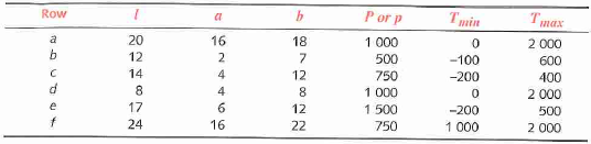
A simply supported shaft is shown in Figure. A constant-magnitude transverse load P is applied as the shaft rotates subject to a time-varying torque that varies from Tmin to Tmax. For ihe data in the row(s) assigned from Table, find the diameter of shaft required to obtain a safety factor of 2 in fatigue loading if the shaft is steel of Sut = 108 kpsi and Sy = 62 kpsi. The dimensions are in inches, the force in pounds, and the torque in lb-in. Assume no stress concentrations are present.
Figure

Table Data for Problems
Homework Answers
Request Answer!
We need at least 10 more requests to produce the answer.
0 / 10 have requested this problem solution
The more requests, the faster the answer.
Add Answer to:
A simply supported shaft is shown in Figure. A constant-magnitude transverse load P is applied as...
A simply supported shaft shown below is subjected to a constant load P and a time varying torque,...
 A simply supported shaft shown below is subjected to a constant load P and a time varying torque, Tmin to Tmax Find the shaft diameter for a factor of safety of 2 for fatigue with the following information for the steel shaft. Se = 180 MPa, Sy = 450 MPa, Sut = 600 MPa P- 5 kN, Tmin 0, Tmax-150 N-m a-400 mm, b 550 mm, I 575 mm
A simply supported shaft shown below is subjected to a constant...
A simply supported shaft shown below is subjected to a constant load P and a time varying torque, Tmin to Tmax Find the shaft diameter for a factor of safety of 2 for fatigue with the following information for the steel shaft. Se = 180 MPa, Sy = 450 MPa, Sut = 600 MPa P- 5 kN, Tmin 0, Tmax-150 N-m a-400 mm, b 550 mm, I 575 mm
A simply supported shaft shown below is subjected to a constant...
Find the normal U a. b. Find the maximum shear stress and plltip c. Find the...
 Find the normal U a. b. Find the maximum shear stress and plltip c. Find the safety factor using the distortion-energy (Von MiSe Problem 2 [20]: A simply supported shaft with overhanging load is shown in Figure 2 force P is applied as the shaft rotates. The shaft is also subject to a constant torque of T ignoring Tmin, find the diameter of shaft required to obtain a safety factor o shaft is steel of Sut - 118 kpsi and...
Problem 2: A) Explain 1) Different types of Keys 2) Interference fit 3) Couplings. 1151 B)...
 Problem 2: A) Explain 1) Different types of Keys 2) Interference fit 3) Couplings. 1151 B) A simply supported shaft is shown in the following Figure. A constant magnitude distributed unit load pis applied as the shaft rotates. The shaft is also subject to a steady torque of Tmax=2000-N m., find the diameter of shaft required to obtain a safety factor of 2.5 in fatigue loading if the shaft is steel of Sut= 814 MPa and Sy = 703 MPa....
A rotating shaft of 25-mm diameter is simply supported by bearing reaction forces R and R. The shaft is loaded with a transverse load of 13 kN as shown in the figure.
 A rotating shaft of 25-mm diameter is simply supported by bearing reaction forces R and R. The shaft is loaded with a transverse load of 13 kN as shown in the figure. The shaft is made from AISI 1045 hot-rolled steel. The surface has been machined. Determine (a) the minimum static factor of safety based on yielding. (b) the endurance limit, adjusted as necessary with Marin factors. (c) the minimum fatigue factor of safety based on achieving infinite life. (d) If the fatigue factor...
The rotating solid steel shaft is simply supported by bearings at points B and C and is driven by gear (not shown) which meshes with the spur gear at D
 The rotating solid steel shaft is simply supported by bearings at points B and C and is driven by gear (not shown) which meshes with the spur gear at D, which has a 150-mm pitch diameter. The force F from the drive gear acts at a pressure angle of 20". The shaft transmits a torque to point A of TA = 340 N.m. The shaft is machined from steel with Sy= 420 MPa and Sut = 560 MPa. The fatigue...
Properties for all problems Sut = 80 ksi, 5= 60 ksi, Sf = 40 ksi, q=0.85...
 Properties for all problems Sut = 80 ksi, 5= 60 ksi, Sf = 40 ksi, q=0.85 (notch sensitivity), steel E = 30e6 psi Remember we use Modified-Goodman for all calculations Problem 1 A 1-inch diameter rod that is 8 inches long has a bearing at one end and another bearing at 6 inches (treat bearings as simple supports). A vertical load is applied at the end of the overhanging rod and a torque is transmitted through the length of the...
Please answer A and B. The rotating solid stedl shaft is simply supported by bearings at...
 Please answer A and B.
The rotating solid stedl shaft is simply supported by bearings at points B and C and is driven by a gear (not shown) which meshes with the spur gear at D, which has a 150-mm pitch diameter. The force F from the drive gear acts at a pressure angle of 20. The shaft transmits a torque to point A of TA-340 N m. The shaft is machined from steel with Sy- 420 MPa and Sut-560...
Please answer A and B.
The rotating solid stedl shaft is simply supported by bearings at points B and C and is driven by a gear (not shown) which meshes with the spur gear at D, which has a 150-mm pitch diameter. The force F from the drive gear acts at a pressure angle of 20. The shaft transmits a torque to point A of TA-340 N m. The shaft is machined from steel with Sy- 420 MPa and Sut-560...
The shaft shown in the figure is driven by a gear at the right keyway, drives...
 The shaft shown in the figure is driven by a gear at the right keyway, drives a fan at the left keyway, and is supported by two deep-groove ball bearings at locations A and B. The shaft is made from AISI 1045 cold-drawn steel. At steady- state speed, the gear transmits a radial load of 300 lbf and a tangential load of 700 lbf at a pitch diameter of 8 in. Assume that the weight and axial load of the...
A simply supported beam is subjected to a load applied as shown in the figure. Draw the shear for...
 A simply supported beam is subjected to a load applied as shown in the figure. Draw the shear force diagram. Consider the section shown and determine (a) the largest shear stress in the section n-n, (b) the shear stress at point a and show this stress on an element. 15,15 30 15,15 20 I n 40 120 15m 0.8 m Dimensions in mm
A simply supported beam is subjected to a load applied as shown in the figure. Draw the...
A simply supported beam is subjected to a load applied as shown in the figure. Draw the shear force diagram. Consider the section shown and determine (a) the largest shear stress in the section n-n, (b) the shear stress at point a and show this stress on an element. 15,15 30 15,15 20 I n 40 120 15m 0.8 m Dimensions in mm
A simply supported beam is subjected to a load applied as shown in the figure. Draw the...
Figure below shows the load components acting on a helical gear mounted on a simply supported...
 Figure below shows the load components acting on a helical gear
mounted on a simply
supported shaft. Bearing B takes thrust. A flexible coupling for
transmitting
torque attaches to the right end of the shaft. The left end is
free.
1-Draw load, shear force, and bending moment diagrams for the
shaft, in both the horizontal and vertical planes.
2- Identify the most critically loaded shaft cross section, and
for this location determine the diameter theoretically required for
infinite life. Assume...
Figure below shows the load components acting on a helical gear
mounted on a simply
supported shaft. Bearing B takes thrust. A flexible coupling for
transmitting
torque attaches to the right end of the shaft. The left end is
free.
1-Draw load, shear force, and bending moment diagrams for the
shaft, in both the horizontal and vertical planes.
2- Identify the most critically loaded shaft cross section, and
for this location determine the diameter theoretically required for
infinite life. Assume...
 A simply supported shaft shown below is subjected to a constant load P and a time varying torque, Tmin to Tmax Find the shaft diameter for a factor of safety of 2 for fatigue with the following information for the steel shaft. Se = 180 MPa, Sy = 450 MPa, Sut = 600 MPa P- 5 kN, Tmin 0, Tmax-150 N-m a-400 mm, b 550 mm, I 575 mm
A simply supported shaft shown below is subjected to a constant...
A simply supported shaft shown below is subjected to a constant load P and a time varying torque, Tmin to Tmax Find the shaft diameter for a factor of safety of 2 for fatigue with the following information for the steel shaft. Se = 180 MPa, Sy = 450 MPa, Sut = 600 MPa P- 5 kN, Tmin 0, Tmax-150 N-m a-400 mm, b 550 mm, I 575 mm
A simply supported shaft shown below is subjected to a constant...
 Find the normal U a. b. Find the maximum shear stress and plltip c. Find the safety factor using the distortion-energy (Von MiSe Problem 2 [20]: A simply supported shaft with overhanging load is shown in Figure 2 force P is applied as the shaft rotates. The shaft is also subject to a constant torque of T ignoring Tmin, find the diameter of shaft required to obtain a safety factor o shaft is steel of Sut - 118 kpsi and...
 Problem 2: A) Explain 1) Different types of Keys 2) Interference fit 3) Couplings. 1151 B) A simply supported shaft is shown in the following Figure. A constant magnitude distributed unit load pis applied as the shaft rotates. The shaft is also subject to a steady torque of Tmax=2000-N m., find the diameter of shaft required to obtain a safety factor of 2.5 in fatigue loading if the shaft is steel of Sut= 814 MPa and Sy = 703 MPa....
 Properties for all problems Sut = 80 ksi, 5= 60 ksi, Sf = 40 ksi, q=0.85 (notch sensitivity), steel E = 30e6 psi Remember we use Modified-Goodman for all calculations Problem 1 A 1-inch diameter rod that is 8 inches long has a bearing at one end and another bearing at 6 inches (treat bearings as simple supports). A vertical load is applied at the end of the overhanging rod and a torque is transmitted through the length of the...
 Please answer A and B.
The rotating solid stedl shaft is simply supported by bearings at points B and C and is driven by a gear (not shown) which meshes with the spur gear at D, which has a 150-mm pitch diameter. The force F from the drive gear acts at a pressure angle of 20. The shaft transmits a torque to point A of TA-340 N m. The shaft is machined from steel with Sy- 420 MPa and Sut-560...
Please answer A and B.
The rotating solid stedl shaft is simply supported by bearings at points B and C and is driven by a gear (not shown) which meshes with the spur gear at D, which has a 150-mm pitch diameter. The force F from the drive gear acts at a pressure angle of 20. The shaft transmits a torque to point A of TA-340 N m. The shaft is machined from steel with Sy- 420 MPa and Sut-560...
 The shaft shown in the figure is driven by a gear at the right keyway, drives a fan at the left keyway, and is supported by two deep-groove ball bearings at locations A and B. The shaft is made from AISI 1045 cold-drawn steel. At steady- state speed, the gear transmits a radial load of 300 lbf and a tangential load of 700 lbf at a pitch diameter of 8 in. Assume that the weight and axial load of the...
 A simply supported beam is subjected to a load applied as shown in the figure. Draw the shear force diagram. Consider the section shown and determine (a) the largest shear stress in the section n-n, (b) the shear stress at point a and show this stress on an element. 15,15 30 15,15 20 I n 40 120 15m 0.8 m Dimensions in mm
A simply supported beam is subjected to a load applied as shown in the figure. Draw the...
A simply supported beam is subjected to a load applied as shown in the figure. Draw the shear force diagram. Consider the section shown and determine (a) the largest shear stress in the section n-n, (b) the shear stress at point a and show this stress on an element. 15,15 30 15,15 20 I n 40 120 15m 0.8 m Dimensions in mm
A simply supported beam is subjected to a load applied as shown in the figure. Draw the...
 Figure below shows the load components acting on a helical gear
mounted on a simply
supported shaft. Bearing B takes thrust. A flexible coupling for
transmitting
torque attaches to the right end of the shaft. The left end is
free.
1-Draw load, shear force, and bending moment diagrams for the
shaft, in both the horizontal and vertical planes.
2- Identify the most critically loaded shaft cross section, and
for this location determine the diameter theoretically required for
infinite life. Assume...
Figure below shows the load components acting on a helical gear
mounted on a simply
supported shaft. Bearing B takes thrust. A flexible coupling for
transmitting
torque attaches to the right end of the shaft. The left end is
free.
1-Draw load, shear force, and bending moment diagrams for the
shaft, in both the horizontal and vertical planes.
2- Identify the most critically loaded shaft cross section, and
for this location determine the diameter theoretically required for
infinite life. Assume...
Most questions answered within 3 hours.
-
You measure 22 dogs' weights, and find they have a mean weight
of 64 ounces. Assume...
asked 4 minutes ago -
Complete and balance the following methesis reaction in aqueous
solution.
Instructions
• Use proper element capitalization....
asked 16 minutes ago -
Green Tree Corporation is expecting to receive $0.5 million at
the end of Year 1, $0.25...
asked 25 minutes ago -
A face value of $10,000 is assumed for these Treasury bills.
Maturity Days to Maturity Bank...
asked 21 minutes ago -
Please read the article attached.Under Armour Is Subject of
Federal Accounting Probes - WSJ.pdf Under Armour,...
asked 18 minutes ago -
An increase in income will usually shift out the demand for a
product.
Group of answer...
asked 22 minutes ago -
What is the correct unit of the spring constant k?
A- N m
B- J/m
C-...
asked 33 minutes ago -
A manufacturing company prepays its insurance coverage for a
three-year period. The premium for the three...
asked 37 minutes ago -
What is the other name for Shortest Job First Preemptive
Algorithm?
What are the 5 different...
asked 50 minutes ago -
24) An outbreak due to exposure of a group of persons to the
same harmful influence...
asked 59 minutes ago -
Show the calculation of (1) the expected grams of alum
(KAl(SO4)2 •12 H2O) formed from the...
asked 1 hour ago -
*There are two different answers posted. Other students
were asked the same question. Which response is...
asked 1 hour ago