
Homework Answers

Add Answer to:
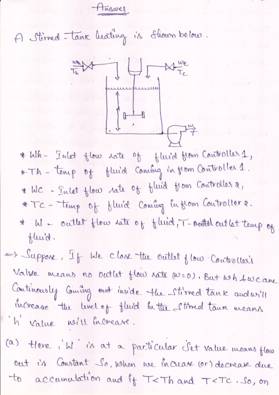
A stirred-tank heating system is shown below. Briefly critique these two control strategies [mark 25 1....
A stirred tank flow reactor is operating in continuous mode (shown below), and an exothermic (heat...
 A stirred tank flow reactor is operating in continuous mode
(shown below), and an exothermic (heat generating) chemical
reaction is taking place inside the reactor. The control objective
is to maintain the concentration of product at a desired value (set
point). The conversion of chemical reaction is highly dependent on
the reaction temperature. To maintain the reaction temperature at
the desired value, a cooling water jacket is used for the reactor.
The major input disturbance is fluctuation in the temperature...
A stirred tank flow reactor is operating in continuous mode
(shown below), and an exothermic (heat generating) chemical
reaction is taking place inside the reactor. The control objective
is to maintain the concentration of product at a desired value (set
point). The conversion of chemical reaction is highly dependent on
the reaction temperature. To maintain the reaction temperature at
the desired value, a cooling water jacket is used for the reactor.
The major input disturbance is fluctuation in the temperature...
year mark worth 30% of your Question 1 Consider a continuous stirred tank reactor system as...
 year mark worth 30% of your Question 1 Consider a continuous stirred tank reactor system as shown below: Reactant CAi F T Coolant F, T Coolant F Tai Product CA, F, T CSTR with cooling jacket A simple exothermic reaction A B takes place in the reactor. The reactor is cooled by a coolant that flows through the jacket around the reactor. The operational objectives Of the system are: to maintain the effluent concentration at the desired value, CAs to...
4 * 165+4)* lyzů + 7 + 2x 1. Consider a two-tank fluid-level control system shown...
 4 * 165+4)* lyzů + 7 + 2x 1. Consider a two-tank fluid-level control system shown below. The level of the second tank is to be controlled. Let hy be the height of the fluid in the first tank and hy be the height of the fluid in the second tank. The input, u is a valve to let fluid into tank 1. The output, y is measurement of hz. A linear model of this system and a first order...
Question 1 Consider a continuous stirred tank reactor system as shown below: Reactant CA F T...
 Question 1 Consider a continuous stirred tank reactor system as shown below: Reactant CA F T Coolant Fo Tco Coolant Product Fo Tdi CA FT CSTR with cooling jacket A simple exothermic reaction A B takes place in the reactor. The reactor is cooled by a coolant that flows through the jacket around the reactor. The operational objectives of the system are: - to maintain the effluent concentration at the desired value, CAs to maintain the effluent temperature at the...
4 (a) Based on the block diagram for a control system (Figure Q4(a) below) determine the...
 4 (a) Based on the block diagram for a control system (Figure Q4(a) below) determine the transfer function between the error and the set point, E(s)/R(s) (8 marks) R(s)+ c(p) m(s) Figure Q4(a) Figure Q4(b) below shows two different control strategies for a continuous stirred tank reactor (CSTR). The reaction A → B is exothermic and the heat generated is removed by the coolant flowing through the jacket. It is assumed the flowrate of the reactor feed is fixed. Two...
Name 4. (25 points) A heating system is shown below. For the system shown, find the...
 Name 4. (25 points) A heating system is shown below. For the system shown, find the final temperature of the air in ºc. a out = 100 W Wein = 10kW Ti = 17°C Pi = 100 kPa m = 3kg/s
In the block diagram of the feedback control system shown in figure below, Gp(s) is the...
 In the block diagram of the feedback control system shown in figure below, Gp(s) is the transfer function of a process, R(s) is reference input, and A(s) and H(s) represent controllers. N(S) R(s) Gp(s) Process A(s) H(s) = _100_ , and H(s)-1 / GAS). Let Gs)-A(S)5.and Find the steady state value of the response C(t), when N(t) = R(t) = unit-step function. Is this also the maximum value attained by the response? Justify your answers. (s2+2s+4)
QUESTION 2 The system shown below is a fermentation tank. In this, water (with dissolved glucose) enters the tank with...
 QUESTION 2 The system shown below is a fermentation tank. In this, water (with dissolved glucose) enters the tank with a flow rate of q: [L/min) and a glucose concentration of c [mol/L). During reaction, glucose is converted at a rate of n = -VKc (where n is the moles of glucose converted per minute [mol/min), V is the volume of fluid in the tank (L'), and K is the reaction rate). The tank has a cross-sectional area of A....
A pump transports water from Tank 1 to Tank 2 through a constant-diameter piping system as...
 A pump transports water from Tank 1 to Tank 2 through a constant-diameter piping system as shown below (not to scale). The flow rate is controlled by two gate valves, the gate valve I controls the main pipeline, while the gate valve II controls the loop line from T-joint A to T-joint B. All pipes are galvanized steel pipe of diameter D = 4 in. It has a total length of Li2= 620 ft from tank 1 to tank 2....
PROBLEMA: (25%) A closed-loop control system is shown below Ds) T(O) U(A) C(s) (a) Show that a proportional controller (C(s)-kp) will never make the closed-loop system stable. (8%) (Hint: you nee...
 PROBLEMA: (25%) A closed-loop control system is shown below Ds) T(O) U(A) C(s) (a) Show that a proportional controller (C(s)-kp) will never make the closed-loop system stable. (8%) (Hint: you need to calculate the closed-loop pole locations and make discussion for the two possible cases.) (Medim) (b) When a PD controller is used (C(s)kp+ kps), calculate the steady state tracking error when both R(s) and D(s) are unit steps. (8%) (Easy) (e) Suppose R(s) is a unit step and D(s)...
 A stirred tank flow reactor is operating in continuous mode
(shown below), and an exothermic (heat generating) chemical
reaction is taking place inside the reactor. The control objective
is to maintain the concentration of product at a desired value (set
point). The conversion of chemical reaction is highly dependent on
the reaction temperature. To maintain the reaction temperature at
the desired value, a cooling water jacket is used for the reactor.
The major input disturbance is fluctuation in the temperature...
A stirred tank flow reactor is operating in continuous mode
(shown below), and an exothermic (heat generating) chemical
reaction is taking place inside the reactor. The control objective
is to maintain the concentration of product at a desired value (set
point). The conversion of chemical reaction is highly dependent on
the reaction temperature. To maintain the reaction temperature at
the desired value, a cooling water jacket is used for the reactor.
The major input disturbance is fluctuation in the temperature...
 year mark worth 30% of your Question 1 Consider a continuous stirred tank reactor system as shown below: Reactant CAi F T Coolant F, T Coolant F Tai Product CA, F, T CSTR with cooling jacket A simple exothermic reaction A B takes place in the reactor. The reactor is cooled by a coolant that flows through the jacket around the reactor. The operational objectives Of the system are: to maintain the effluent concentration at the desired value, CAs to...
 4 * 165+4)* lyzů + 7 + 2x 1. Consider a two-tank fluid-level control system shown below. The level of the second tank is to be controlled. Let hy be the height of the fluid in the first tank and hy be the height of the fluid in the second tank. The input, u is a valve to let fluid into tank 1. The output, y is measurement of hz. A linear model of this system and a first order...
 Question 1 Consider a continuous stirred tank reactor system as shown below: Reactant CA F T Coolant Fo Tco Coolant Product Fo Tdi CA FT CSTR with cooling jacket A simple exothermic reaction A B takes place in the reactor. The reactor is cooled by a coolant that flows through the jacket around the reactor. The operational objectives of the system are: - to maintain the effluent concentration at the desired value, CAs to maintain the effluent temperature at the...
 4 (a) Based on the block diagram for a control system (Figure Q4(a) below) determine the transfer function between the error and the set point, E(s)/R(s) (8 marks) R(s)+ c(p) m(s) Figure Q4(a) Figure Q4(b) below shows two different control strategies for a continuous stirred tank reactor (CSTR). The reaction A → B is exothermic and the heat generated is removed by the coolant flowing through the jacket. It is assumed the flowrate of the reactor feed is fixed. Two...
 Name 4. (25 points) A heating system is shown below. For the system shown, find the final temperature of the air in ºc. a out = 100 W Wein = 10kW Ti = 17°C Pi = 100 kPa m = 3kg/s
 In the block diagram of the feedback control system shown in figure below, Gp(s) is the transfer function of a process, R(s) is reference input, and A(s) and H(s) represent controllers. N(S) R(s) Gp(s) Process A(s) H(s) = _100_ , and H(s)-1 / GAS). Let Gs)-A(S)5.and Find the steady state value of the response C(t), when N(t) = R(t) = unit-step function. Is this also the maximum value attained by the response? Justify your answers. (s2+2s+4)
 QUESTION 2 The system shown below is a fermentation tank. In this, water (with dissolved glucose) enters the tank with a flow rate of q: [L/min) and a glucose concentration of c [mol/L). During reaction, glucose is converted at a rate of n = -VKc (where n is the moles of glucose converted per minute [mol/min), V is the volume of fluid in the tank (L'), and K is the reaction rate). The tank has a cross-sectional area of A....
 A pump transports water from Tank 1 to Tank 2 through a constant-diameter piping system as shown below (not to scale). The flow rate is controlled by two gate valves, the gate valve I controls the main pipeline, while the gate valve II controls the loop line from T-joint A to T-joint B. All pipes are galvanized steel pipe of diameter D = 4 in. It has a total length of Li2= 620 ft from tank 1 to tank 2....
 PROBLEMA: (25%) A closed-loop control system is shown below Ds) T(O) U(A) C(s) (a) Show that a proportional controller (C(s)-kp) will never make the closed-loop system stable. (8%) (Hint: you need to calculate the closed-loop pole locations and make discussion for the two possible cases.) (Medim) (b) When a PD controller is used (C(s)kp+ kps), calculate the steady state tracking error when both R(s) and D(s) are unit steps. (8%) (Easy) (e) Suppose R(s) is a unit step and D(s)...
Most questions answered within 3 hours.
-
Which has the highest energy photons in each pair? a. light with
a wavelength of 5x10^3m...
asked 1 minute ago -
1. When a TLC plate was developed, detection by UV
light showed a single spot at the...
asked 2 minutes ago -
What is the source of information from natural materials which
can be used to reconstruct climate...
asked 18 minutes ago -
The International Monetary Fund (IMF) has hired you as an
economist. Your assignment is to travel...
asked 22 minutes ago -
Brief Exercise 12-65
Profitability Ratios
Tinker Corporation operates in the highly competitive consulting
industry. Tinker's balance...
asked 47 minutes ago -
Consider Lewin's three-step process. Which of the three steps do
you thin would be hardest to...
asked 47 minutes ago -
A disabled tanker leaks kerosene (n = 1.20) into the
Persian Gulf, creating a large slick...
asked 1 hour ago -
5. Explain the condition for a DC motor to develop the
maximum power. If a DC...
asked 1 hour ago -
Compute the p[Ag] after 35.00 mL of 0.1 M silver nitrate has been
added to the...
asked 1 hour ago -
Walgreen Company (NYSE: WAG) is currently trading at $48.50 on
the NYSE. Walgreen Company is also...
asked 1 hour ago -
Based on historical data, your team knows what proportion of the
company's orders come from Males...
asked 1 hour ago -
8. Which of the following atoms has the largest magnitude
electron affinity?
(a) Sodium (Na)
(b)...
asked 1 hour ago