Now let’s apply Kirchhoff’s rules to a simple battery circuit.
The circuit, shown in (Figure 1), is used to start a car that has a
weak (i.e., nearly discharged) battery (Figure 2). It includes two
batteries, each with an emf and an internal resistance, and two
resistors. Find the current in the circuit and the potential
difference Vab. In this example, if the emf of the 4 V battery is
increased to 16 V and the rest of the circuit remains the same,
what is the potential difference Vab?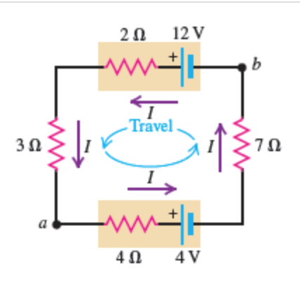
Homework Answers

Add Answer to:
Now let’s apply Kirchhoff’s rules to a simple battery circuit.
The circuit, shown in (Figure 1),...
1. Kirchoff's Rules See Figure 1. The circuit consists of two batteries and five resistors. The...
 1. Kirchoff's Rules See Figure 1. The circuit consists of two batteries and five resistors. The terminal voltage of each battery is specified and the resistance value of each resistor is given. Find the potential difference Vab, that is, V- Va. 2. Electric Potential R -1. R24 Ryan cizut Voilor R,= R₂:22 R₂=R4 = 4.2 Rs = 3.0 V. - 5 V, 20v Figure 1 Figure 4 C, C-1 uf Ccy 2uF V-10v Figure 5 Figure 2 Figure 6 C-2...
R E, In the figure , battery 1 has emf E1 = 12.0V and internal resistance...
 R E, In the figure , battery 1 has emf E1 = 12.0V and internal resistance rı = 0.016 Ohms and battery 2 has emf E2 = 12.0V and internal resistance r2 = 0.014 Ohms. The batteries are connected in series with an external resistance R. What R value in ohms makes the terminal-to- terminal potential difference of one of the batteries zero?
In the circuit shown in the figure (Figure 1) the batteries have negligible internal resistance and the meters are both idealized.
 In the circuit shown in the figure (Figure 1) the batteries have negligible internal resistance and the meters are both idealized. With the switch S open, the voltmeter reads 13.0 V. Find the emf epsilon of the battery. What will the ammeter read when the switch is closed?
Constants Now we will tackle a more complex two-loop circuit using Kirchhoff's rules. In the circuit...
 Constants Now we will tackle a more complex two-loop circuit using Kirchhoff's rules. In the circuit shown in (Figure 1), a 12 V power supply with unknown resistance r (represented as a battery) is connected to a run-down rechargeable battery with unknown emf e and internal resistance 1 and to a bulb with resistance 3 2 The current through the bulb is 2 A, and the current in the run- down battery is 1 A; the directions of both of...
In the circuit of the figure below, the battery emf e m f is 60 V,...
 In the circuit of the figure
below, the battery emf e m f is 60 V, the resistance R is 150 Ω,
and the capacitance C is 0.500 µF. The switch S is closed for a
long time interval, and zero potential difference is measured
across the capacitor. After the switch is opened, the potential
difference across the capacitor reaches a maximum value of 150 V.
What is the value of the inductance?
In the circuit of the figure below,...
In the circuit of the figure
below, the battery emf e m f is 60 V, the resistance R is 150 Ω,
and the capacitance C is 0.500 µF. The switch S is closed for a
long time interval, and zero potential difference is measured
across the capacitor. After the switch is opened, the potential
difference across the capacitor reaches a maximum value of 150 V.
What is the value of the inductance?
In the circuit of the figure below,...
Consider the circuit shown in the figure(Figure 1). Suppose thefour resistors in this circuit have...
 Consider the circuit shown in the figure(Figure 1). Suppose the
four resistors in this circuit have the values R1 = 10 Ω , R2 = 6.6
Ω , R3 = 6.1 Ω , and R4 = 14 Ω , and that the emf of the battery is
E = 18 V .Find the current through each resistor using the rules for
series and parallel resistors.Find the current through each resistor using Kirchhoff's
rules.
Consider the circuit shown in the figure(Figure 1). Suppose the
four resistors in this circuit have the values R1 = 10 Ω , R2 = 6.6
Ω , R3 = 6.1 Ω , and R4 = 14 Ω , and that the emf of the battery is
E = 18 V .Find the current through each resistor using the rules for
series and parallel resistors.Find the current through each resistor using Kirchhoff's
rules.
3. An electric circuit consists of a battery, three 2 12 resistors and a 10 A...
 3. An electric circuit consists of a battery, three 2 12 resistors and a 10 A fuse. 12V 2Ω Calculate the total current out of the battery. If the current through the fuse exceeds 10 A, assume that it melts and opens the circuit. a) Determine the amount of charge that flows between the top two resistors at point B during a period of 5 seconds. b) c) Assume that the potential on the batteries positive terminal to be 12...
You connect five identical resistors in series to a battery whose EMF is 12.0 V and...
You connect five identical resistors in series to a battery whose EMF is 12.0 V and whose internal resistance is negligible. You measure the current that the circuit draws from the battery and find 0.981 A. What are the resistance of each resistor and the potential difference across each resistor?
Constants 1 Periodic Table The circuit in the figure (Figure 1) includes a battery with ante...
 Constants 1 Periodic Table The circuit in the figure (Figure 1) includes a battery with ante internal resistance, 0.55 A Submit Request Answer Part C How much current flows through the battery? Express your answer using two significant figures. 0 ΑΣΦ Submit Request Answer Part D Figure 1 of What is the potential difference between the terminals of the battery? 1.00 7.10 ΑΣΦ 3 450 33.20 Very 5.80 WWF Submit Request Answer Provide Feedback ΝΟΧΙ Σ DA A 00m NOV...
A circuit is constructed with five resistors and one real battery as shown above right. We...
 A circuit is constructed with
five resistors and one real battery as shown above right. We model.
The real battery as an ideal emf V = 12 V in series with an
internal resistance r as shown above left. The values for the
resistors are: R1 = R3 = 22 Ω, R4 = R5 = 82 Ω and R2 = 147 Ω. The
measured voltage across the terminals of the batery is Vbattery =
11.6 V.
A circuit is constructed...
A circuit is constructed with
five resistors and one real battery as shown above right. We model.
The real battery as an ideal emf V = 12 V in series with an
internal resistance r as shown above left. The values for the
resistors are: R1 = R3 = 22 Ω, R4 = R5 = 82 Ω and R2 = 147 Ω. The
measured voltage across the terminals of the batery is Vbattery =
11.6 V.
A circuit is constructed...
 1. Kirchoff's Rules See Figure 1. The circuit consists of two batteries and five resistors. The terminal voltage of each battery is specified and the resistance value of each resistor is given. Find the potential difference Vab, that is, V- Va. 2. Electric Potential R -1. R24 Ryan cizut Voilor R,= R₂:22 R₂=R4 = 4.2 Rs = 3.0 V. - 5 V, 20v Figure 1 Figure 4 C, C-1 uf Ccy 2uF V-10v Figure 5 Figure 2 Figure 6 C-2...
 R E, In the figure , battery 1 has emf E1 = 12.0V and internal resistance rı = 0.016 Ohms and battery 2 has emf E2 = 12.0V and internal resistance r2 = 0.014 Ohms. The batteries are connected in series with an external resistance R. What R value in ohms makes the terminal-to- terminal potential difference of one of the batteries zero?
 Constants Now we will tackle a more complex two-loop circuit using Kirchhoff's rules. In the circuit shown in (Figure 1), a 12 V power supply with unknown resistance r (represented as a battery) is connected to a run-down rechargeable battery with unknown emf e and internal resistance 1 and to a bulb with resistance 3 2 The current through the bulb is 2 A, and the current in the run- down battery is 1 A; the directions of both of...
 In the circuit of the figure
below, the battery emf e m f is 60 V, the resistance R is 150 Ω,
and the capacitance C is 0.500 µF. The switch S is closed for a
long time interval, and zero potential difference is measured
across the capacitor. After the switch is opened, the potential
difference across the capacitor reaches a maximum value of 150 V.
What is the value of the inductance?
In the circuit of the figure below,...
In the circuit of the figure
below, the battery emf e m f is 60 V, the resistance R is 150 Ω,
and the capacitance C is 0.500 µF. The switch S is closed for a
long time interval, and zero potential difference is measured
across the capacitor. After the switch is opened, the potential
difference across the capacitor reaches a maximum value of 150 V.
What is the value of the inductance?
In the circuit of the figure below,...
 Consider the circuit shown in the figure(Figure 1). Suppose the
four resistors in this circuit have the values R1 = 10 Ω , R2 = 6.6
Ω , R3 = 6.1 Ω , and R4 = 14 Ω , and that the emf of the battery is
E = 18 V .Find the current through each resistor using the rules for
series and parallel resistors.Find the current through each resistor using Kirchhoff's
rules.
Consider the circuit shown in the figure(Figure 1). Suppose the
four resistors in this circuit have the values R1 = 10 Ω , R2 = 6.6
Ω , R3 = 6.1 Ω , and R4 = 14 Ω , and that the emf of the battery is
E = 18 V .Find the current through each resistor using the rules for
series and parallel resistors.Find the current through each resistor using Kirchhoff's
rules.
 3. An electric circuit consists of a battery, three 2 12 resistors and a 10 A fuse. 12V 2Ω Calculate the total current out of the battery. If the current through the fuse exceeds 10 A, assume that it melts and opens the circuit. a) Determine the amount of charge that flows between the top two resistors at point B during a period of 5 seconds. b) c) Assume that the potential on the batteries positive terminal to be 12...
 Constants 1 Periodic Table The circuit in the figure (Figure 1) includes a battery with ante internal resistance, 0.55 A Submit Request Answer Part C How much current flows through the battery? Express your answer using two significant figures. 0 ΑΣΦ Submit Request Answer Part D Figure 1 of What is the potential difference between the terminals of the battery? 1.00 7.10 ΑΣΦ 3 450 33.20 Very 5.80 WWF Submit Request Answer Provide Feedback ΝΟΧΙ Σ DA A 00m NOV...
 A circuit is constructed with
five resistors and one real battery as shown above right. We model.
The real battery as an ideal emf V = 12 V in series with an
internal resistance r as shown above left. The values for the
resistors are: R1 = R3 = 22 Ω, R4 = R5 = 82 Ω and R2 = 147 Ω. The
measured voltage across the terminals of the batery is Vbattery =
11.6 V.
A circuit is constructed...
A circuit is constructed with
five resistors and one real battery as shown above right. We model.
The real battery as an ideal emf V = 12 V in series with an
internal resistance r as shown above left. The values for the
resistors are: R1 = R3 = 22 Ω, R4 = R5 = 82 Ω and R2 = 147 Ω. The
measured voltage across the terminals of the batery is Vbattery =
11.6 V.
A circuit is constructed...
Most questions answered within 3 hours.
-
Each row of the table below describes an aqueous solution at
25°C
.
The second column...
asked 2 minutes ago -
A horizontal wire is at y = 0. Current travels in the +x
direction. The magnetic...
asked 2 minutes ago -
Let X be a continuous random variable whose PDF is Let X be a
continuous random...
asked 23 minutes ago -
Martinez Company’s relevant range of production is 7,500 units
to 12,500 units. When it produces and...
asked 21 minutes ago -
A football with a mass of 1.2 kg is kicked from ground level to
a height...
asked 27 minutes ago -
Remember: Changes in supply determinants shift supply, and
changes in demand determinants shift demand. We say...
asked 25 minutes ago -
Why is the answer b), for this question? I came up with C) for
my incorrect...
asked 32 minutes ago -
Suppose that you know that in the population of full-time
employees in the United States, the...
asked 53 minutes ago -
This experiment was designed originally to sample various meat and carcass quality
aspects of Ontario pigs...
asked 54 minutes ago -
Dopamine Hydrochloride: draw the structure And Show the
functional groups in different colors and label the...
asked 46 minutes ago -
A rope supports a 10 kg dumbbell hanging from it. What is the
tension in the...
asked 46 minutes ago -
) Raw materials are studied for contamination. Suppose that
the number of particles of contamination per...
asked 1 hour ago