
Homework Answers

Add Answer to:
In the circuit shown in Figure 6(b), an emf source E = 12 V and resistance...
The circuit in the figure below contains two resistors, R1-1.8 kΩ and R2 2.8 k. and...
 The circuit in the figure below contains two resistors, R1-1.8 kΩ and R2 2.8 k. and two capacitors, C1-1.7 μF and C3 = 2.5 μF, connected to a battery with emf ε-105 v. If there are no charges on the capacitors before switch s is closed, determine the charges q1 and q2 on capacitors C1 and C2, respectively, as functions of time, after the switch is closed. Hint: First reconstruct the circuit so that it becomes a simple RC circuit...
Question 3 2 pts In the circuit shown below, the emf of the battery E =17...
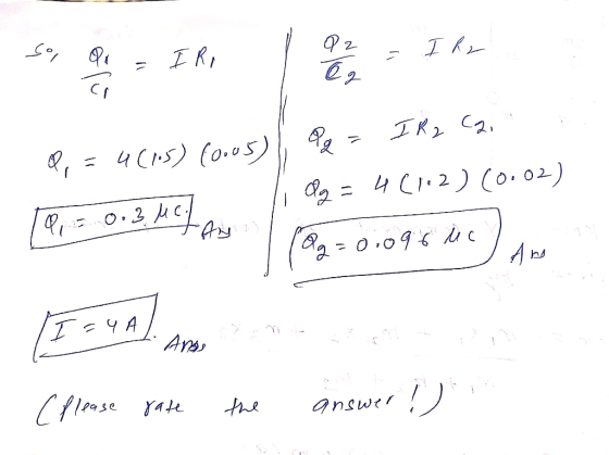
 Question 3 2 pts In the circuit shown below, the emf of the battery E =17 volts; the resistors have values R1 = 196 12 and R2 = 145 N2; and the capacitors have capacitances C1 = 4 uF (microfarads) and C2 = 4 MF. After the switch has been closed for a long time, what is the charge, in uC (microcoulumbs) to the nearest uč, on capacitor 1 (C1)? S CE ES w C2 RE w R
Problem 21 Consider the circuit shown in the following figure. The battery has emf 56.0 V...
 Problem 21 Consider the circuit shown in the following figure. The battery has emf 56.0 V and negligible internal resistance. R2 = 1.00 12 , C1 = 3.00 uF, and C2 = 6.00 uF. After the capacitors have attained their final charges, the charge on C1 is Q1 = 17.0 4C. (Figure 1) What is the final charge on C2 ? Express your answer with the appropriate units. T: A Q2 = Value A O 2 Units ? | Submit...
Consider the circuit shown in (Figure 1). The battery has emf92.0 V and negligible internal...
 Consider the circuit shown in (Figure 1). The battery has emf
92.0 V and negligible internal resistance. R2 = 2.00 Ω , C1 = 3.00
μF , and C2 = 7.00 μF . After the capacitors have attained their
final charges, the charge on C1 is Q1 = 21.0 μCWhat is the final charge on C2?Express your answer with the appropriate units.What is the resistance R1?Express your answer with the appropriate units.
Consider the circuit shown in (Figure 1). The battery has emf
92.0 V and negligible internal resistance. R2 = 2.00 Ω , C1 = 3.00
μF , and C2 = 7.00 μF . After the capacitors have attained their
final charges, the charge on C1 is Q1 = 21.0 μCWhat is the final charge on C2?Express your answer with the appropriate units.What is the resistance R1?Express your answer with the appropriate units.
Roi Luis In the circuit in the figure emf of the battery E = 27 V....
 Roi Luis In the circuit in the figure emf of the battery E = 27 V. All the inductors are of the L same inductance, L=0.12 H and of negligible resistances. Resistances of the resistors are Ro 312, R1 412, R2 101, Ry = 152, R2 12N, Rs = 101, Ro = 10 12. The switch S is closed at the time t = 0. Find the current flowing in Ro immediately after the switch S is closed. Ls 0.75...
In the circuit shown below, the emf of the battery E=42 volts; the resistors have values...
 In the circuit shown below, the emf of the battery E=42 volts; the resistors have values R1 = 116 12, R2 = 184 12, and R3 = 139 N; and the capacitor has a capacitance C = 5 UF (microfarads). After the switch has been closed for a long time, what is the current supplied to the circuit by the battery? Answer in milliamps to the nearest milliamp, where 1000 milliamps = 1 amp. S R} E I RA С...
Consider a RC circuit with Vi 20 V, R, = 100 and R2 = 200 ....
 Consider a RC circuit with Vi 20 V, R, = 100 and R2 = 200 . The capacitors are C, = 12 uF and C2 = 40 uF. The switch in the Figure 6(b) has been closed at position a for a long time. b а R Figure 6(b) What is the amount of electrical energy stored in the capacitor? (i) ANS: The switch is now flipped to position b and remains in position b for a long (ii) time....
In the circuit in the figure R. RS emf of the battery E = 27 V....
 In the circuit in the figure R. RS emf of the battery E = 27 V. All the inductors are of the ZR L same inductance, L=0.12 H L3 R1 and of negligible resistances. Is.. Resistances of the resistors are Ro = 31, R: = 41, R2 = 109, Rg = 1522, R = 122, Rs = 102, R=1012. The switch S is closed at the time t = 0 Find the current flowing in Ro immediately after the switch...
 The circuit in the figure below contains two resistors, R1-1.8 kΩ and R2 2.8 k. and two capacitors, C1-1.7 μF and C3 = 2.5 μF, connected to a battery with emf ε-105 v. If there are no charges on the capacitors before switch s is closed, determine the charges q1 and q2 on capacitors C1 and C2, respectively, as functions of time, after the switch is closed. Hint: First reconstruct the circuit so that it becomes a simple RC circuit...
 Question 3 2 pts In the circuit shown below, the emf of the battery E =17 volts; the resistors have values R1 = 196 12 and R2 = 145 N2; and the capacitors have capacitances C1 = 4 uF (microfarads) and C2 = 4 MF. After the switch has been closed for a long time, what is the charge, in uC (microcoulumbs) to the nearest uč, on capacitor 1 (C1)? S CE ES w C2 RE w R
 Problem 21 Consider the circuit shown in the following figure. The battery has emf 56.0 V and negligible internal resistance. R2 = 1.00 12 , C1 = 3.00 uF, and C2 = 6.00 uF. After the capacitors have attained their final charges, the charge on C1 is Q1 = 17.0 4C. (Figure 1) What is the final charge on C2 ? Express your answer with the appropriate units. T: A Q2 = Value A O 2 Units ? | Submit...
 Consider the circuit shown in (Figure 1). The battery has emf
92.0 V and negligible internal resistance. R2 = 2.00 Ω , C1 = 3.00
μF , and C2 = 7.00 μF . After the capacitors have attained their
final charges, the charge on C1 is Q1 = 21.0 μCWhat is the final charge on C2?Express your answer with the appropriate units.What is the resistance R1?Express your answer with the appropriate units.
Consider the circuit shown in (Figure 1). The battery has emf
92.0 V and negligible internal resistance. R2 = 2.00 Ω , C1 = 3.00
μF , and C2 = 7.00 μF . After the capacitors have attained their
final charges, the charge on C1 is Q1 = 21.0 μCWhat is the final charge on C2?Express your answer with the appropriate units.What is the resistance R1?Express your answer with the appropriate units.
 Roi Luis In the circuit in the figure emf of the battery E = 27 V. All the inductors are of the L same inductance, L=0.12 H and of negligible resistances. Resistances of the resistors are Ro 312, R1 412, R2 101, Ry = 152, R2 12N, Rs = 101, Ro = 10 12. The switch S is closed at the time t = 0. Find the current flowing in Ro immediately after the switch S is closed. Ls 0.75...
 In the circuit shown below, the emf of the battery E=42 volts; the resistors have values R1 = 116 12, R2 = 184 12, and R3 = 139 N; and the capacitor has a capacitance C = 5 UF (microfarads). After the switch has been closed for a long time, what is the current supplied to the circuit by the battery? Answer in milliamps to the nearest milliamp, where 1000 milliamps = 1 amp. S R} E I RA С...
 Consider a RC circuit with Vi 20 V, R, = 100 and R2 = 200 . The capacitors are C, = 12 uF and C2 = 40 uF. The switch in the Figure 6(b) has been closed at position a for a long time. b а R Figure 6(b) What is the amount of electrical energy stored in the capacitor? (i) ANS: The switch is now flipped to position b and remains in position b for a long (ii) time....
 In the circuit in the figure R. RS emf of the battery E = 27 V. All the inductors are of the ZR L same inductance, L=0.12 H L3 R1 and of negligible resistances. Is.. Resistances of the resistors are Ro = 31, R: = 41, R2 = 109, Rg = 1522, R = 122, Rs = 102, R=1012. The switch S is closed at the time t = 0 Find the current flowing in Ro immediately after the switch...
Most questions answered within 3 hours.
-
2) You are given the task of finding a representation for a
circle in a drawing...
asked 27 seconds ago -
1. An object weighing 40 N rests on a surface. The coefficient
of friction is 0.35....
asked 1 hour ago -
Investor company owns 35% of investee company voting stock and
accounts for the investment under the...
asked 2 hours ago -
The number of major faults on a randomly chosen 1 km stretch of
highway has a...
asked 2 hours ago -
Consider the competitive environment of Starbuck's, Progressive
Insurance, a manufacturing firm with low turnover, or a...
asked 3 hours ago -
3. Gains from trade
Consider two neighbouring island countries called Euphoria and
Contente. They each have...
asked 5 hours ago -
A business executive has the option to invest money in two
plans: Plan A guarantees that...
asked 7 hours ago -
Hello, can someone please help me answer this question?
How much heat is absorbed by a...
asked 7 hours ago -
. A marketing researcher conducted a survey of 25 shoppers
randomly selected at the local mall...
asked 7 hours ago -
Create an comprehensive response to the
following:
Antimicrobial agents work on a multitude of microbes (bacteria,...
asked 7 hours ago -
6.13 LAB: Step counter. Section 6.3.
A pedometer treats walking 2,000 steps as walking 1 mile....
asked 7 hours ago -
(14.2) A block of mass m = 10 kg riding on a frictionless
horizontal plane is...
asked 7 hours ago