


can anyone help with this?
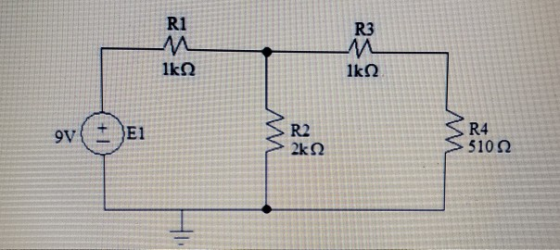
V1 V3 R1 R3 A1 A3 1k2 lkQ A2 A4 SR2 SR4 510 2 V4 V2 9V E1 2kn tho reltago VE across the battery in the appropriate column of Item W
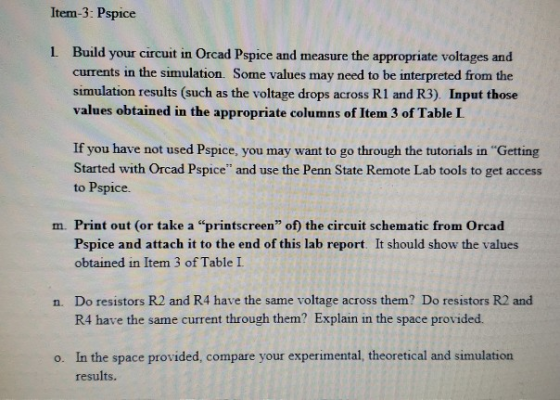
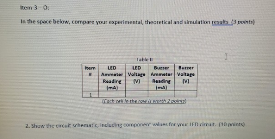
Item-3: Pspice L Build your circuit in Orcad Pspice and measure the appropriate voltages and currents in the simulation. Some values may need to be interpreted from the simulation results (such as the voltage drops across R1 and R3). Input those values obtained in the appropriate columns of Item 3 of Table L If you have not used Pspice, you may want to go through the tutorials in "Getting Started with Orcad Pspice" and use the Penn State Remote Lab tools to get access Pspice. to Print out (or take Pspice and attach it to the end of this lab report. It should show the values obtained in Item 3 of Table I "printscreen" of) the circuit schematic from Orcad m a n. Do resistors R2 and R4 have the same voltage across them? Do resistors R2 and R4 have the same current through them? Explain in the space provided. o. In the space provided, compare your experimental, theoretical and simulation results.
2. Design a circuit to provide 1mA of current through the buzzer and 10mA of current through the red LED. Some trial and error (an iterative approach) may be necessary. Refer to Lab 3 for a refresher on the red LED. You don't have to provide a circuit like the one earlier. Indicate how you solved the problem, including providing a circuit schematic of your system Record the measured values of current through the LED and buzzer in the appropriate columns of Table II. Determine the voltage both the buzzer and the LED with the circuit working, and record in the appropriate columns of Table II. across Feel free to use any of the following online schematic drawing tools: www.circuitlab.com/editor http://www.digikey.com/schemeit#
Item-3- M: a screen capture of the Pspice simulation. (10 points) Include shoodbonsan Item-3- N: voltage across them? Do resistors R2 and R4 have the Do resistors R2 and R4 have the same same current through them? Explain in the space below. (4 points)
Homework Answers
![Voltages/Currents Q100% .84mA T AM1 2.08mA AM2 C 276mA AM3 AM4 LE11,0). |R1(4,5 R212,0] _R3{5,7] |R4[3,0] V_AM114 V AM215,2 V](http://img.homeworklib.com/images/013ac350-f6ae-4550-84d1-4a37b154324f.png?x-oss-process=image/resize,w_560)
As we can see from table
NO resistors R2 and R4 dont have same voltage or current
if we see the circuit with out ammeter or voltmeter we can tell resistors R2 is in parallel connection with resistors R3 and R4 which are in series there fore voltage across R2 will be same as sum of voltage of R3 and R4 not R4 only. Current in R2 and R4 will be equal if resistor value of R2 is equal to sum of resistor value of R3 and R4 here R2 is 2k ohms and R3+R4 is 1.51K ohms which are not equal, there fore their current are not equal.


Consider a circuit with four resistors in series. R1 R2 R3 R4 The battery has a...
 Consider a circuit with four resistors in series. R1 R2 R3 R4 The battery has a voltage of 12 V. The resistor values are R1-800 Ω. R2-600 Ω R3-500 Q . R4-500Q Complete the following table by noting the voltage drop across each listed resistor. Resistor (Q) Voltage Drop (V) R1 00Select R3500Select ] 00 Select ] R2 R4
Consider the circuit below. R1 = 3 ohms, R2 = 6 ohms, R3 = 2 ohms,...
 Consider the circuit below. R1 = 3 ohms, R2 = 6 ohms, R3 = 2
ohms, R4 = 4 ohms, and the battery has a voltage of 12 V. Answer
the following
Pick the best answer for each True/False answer
1. R1 and R2 will both have a voltage across each of 12V. True
or False.
2. R1 and R2 will both have the same current traveling through
them. True or False.
3. R3 and R4 will both have a...
Consider the circuit below. R1 = 3 ohms, R2 = 6 ohms, R3 = 2
ohms, R4 = 4 ohms, and the battery has a voltage of 12 V. Answer
the following
Pick the best answer for each True/False answer
1. R1 and R2 will both have a voltage across each of 12V. True
or False.
2. R1 and R2 will both have the same current traveling through
them. True or False.
3. R3 and R4 will both have a...
1. Find the voltage across resistor R3 R4 Sko V1 R3 - 12 $1. 00 2....
 1. Find the voltage across resistor R3 R4 Sko V1 R3 - 12 $1. 00 2. Find the current through and voltage across R6 R1 R2 1.sk = V2 12V 1.00 R4 R8 4700 1.Ok R7 $1.0ko R6 2.25kn 3. Find the voltage across and current through R3 R1 R2 4.7k 1.Ok 12V 1.5k) R5 W 4.7kQ R4 WW 1.5k R6 4. Find the voltage across R2 and the current through R6 R7 R5 R3 1.0k 1.0kg vi 12V R6...
Suppose R1=4Ω, R2=2Ω, R3=8Ω, R4=10Ω, 5=6Ω, R6=16Ω, E1=9V and E2=11V. Part A: Use Kirchhoff's voltage law...
 Suppose R1=4Ω, R2=2Ω, R3=8Ω, R4=10Ω, 5=6Ω, R6=16Ω, E1=9V and
E2=11V.
Part A:
Use Kirchhoff's voltage law to find an equation for the voltage
drop around loop 3
Part B:
Find the loop currents i1i1, i2i2 and i3i3 (positive for
clockwise direction)
Part C:
Which direction does current flow across each of the resistors?
Match with the following choices.
Possible choices :
A:from left to right
B: from right to left
C: no current
D: from top to bottom
E: from...
Suppose R1=4Ω, R2=2Ω, R3=8Ω, R4=10Ω, 5=6Ω, R6=16Ω, E1=9V and
E2=11V.
Part A:
Use Kirchhoff's voltage law to find an equation for the voltage
drop around loop 3
Part B:
Find the loop currents i1i1, i2i2 and i3i3 (positive for
clockwise direction)
Part C:
Which direction does current flow across each of the resistors?
Match with the following choices.
Possible choices :
A:from left to right
B: from right to left
C: no current
D: from top to bottom
E: from...
R1 R3 R2 R4 W The circuit in the diagram contains one battery and four resistors,...
 R1 R3 R2 R4 W The circuit in the diagram contains one battery and four resistors, labeled 1 through 4. ?Which of the following is true about the way that the circuit elements are arranged Resistors 1 and 2 are in parallel while resistors 3 and 4 are in series Resistors 1 and 4 are in parallel while resistors 2 and 3 are in series Resistors 1 and 4 are in series, while resistors 2 and 3 are in parallel...
R1 1.5K R3 3K V1 50V R2 6k R4 6K R1 Total R2 R3 R4 Current...
 R1 1.5K R3 3K V1 50V R2 6k R4 6K R1 Total R2 R3 R4 Current Voltage Resistance 1.5K Power NA 6K 3K 6K
R1 VB1 VB2 5R5 R2 R4 In the circuit above, the current through R5 (labeled as...
 R1 VB1 VB2 5R5 R2 R4 In the circuit above, the current through R5 (labeled as I5) is 15 mA. Given this information, find the magnitude of the current through the other resistors and the magnitude of the voltage drop across the second battery VB2 VB1 = 3 volts I5 15 mA R1 160Ω R2 = 300Ω R3 = 450Ω R4 270 R4 VB2
5. Consider the next circuit with R1 1 kQ, R2 2.2 kQ, R3 3.3 kQ, R4 4.7 kQ and E 10V Using the Oh...
 5. Consider the next circuit with R1 1 kQ, R2 2.2 kQ, R3 3.3 kQ, R4 4.7 kQ and E 10V Using the Ohm's law, determine the currents through each of the four resistors and record the values in the next table under the Theory column. Note that the larger the resistor, the smaller the current should be. Also determine and record the total supplied current and the current IX Note that this current should equal the sum of the...
E: 10 R1: 2.2k ohm R2: 4.6k ohm R3: 3.3k ohm R4: 6.8k ohm Questions to...
 E: 10
R1: 2.2k ohm
R2: 4.6k ohm
R3: 3.3k ohm
R4: 6.8k ohm
Questions to Answer: 01: Choose the appropriate resistors and voltage sources and find the thevenin voltage and thevenin resistance both theoretically and practically and verify your results. Consider Raas the load resistance. Demonstrate all the working b. a. Fill the tables with appropriate measured and calculate values. Draw the thevenized circuit c. Original Circuit: R Load) VLoad Theory Vond Experimental Deviation R1 R3 R2 R4 Thevenized...
E: 10
R1: 2.2k ohm
R2: 4.6k ohm
R3: 3.3k ohm
R4: 6.8k ohm
Questions to Answer: 01: Choose the appropriate resistors and voltage sources and find the thevenin voltage and thevenin resistance both theoretically and practically and verify your results. Consider Raas the load resistance. Demonstrate all the working b. a. Fill the tables with appropriate measured and calculate values. Draw the thevenized circuit c. Original Circuit: R Load) VLoad Theory Vond Experimental Deviation R1 R3 R2 R4 Thevenized...
Problem 3: Determine explicitly the voltage across R3 in the circuit below R2 R1 R3 R4...
 Problem 3: Determine explicitly the voltage across R3 in the circuit below R2 R1 R3 R4 (Hint: R2 and R3 are in parallel with R1... this combination is in series with R4. The total resistance can give you the total voltage drop AND then you can just analyze as a voltage divider.)
 Consider a circuit with four resistors in series. R1 R2 R3 R4 The battery has a voltage of 12 V. The resistor values are R1-800 Ω. R2-600 Ω R3-500 Q . R4-500Q Complete the following table by noting the voltage drop across each listed resistor. Resistor (Q) Voltage Drop (V) R1 00Select R3500Select ] 00 Select ] R2 R4
 Consider the circuit below. R1 = 3 ohms, R2 = 6 ohms, R3 = 2
ohms, R4 = 4 ohms, and the battery has a voltage of 12 V. Answer
the following
Pick the best answer for each True/False answer
1. R1 and R2 will both have a voltage across each of 12V. True
or False.
2. R1 and R2 will both have the same current traveling through
them. True or False.
3. R3 and R4 will both have a...
Consider the circuit below. R1 = 3 ohms, R2 = 6 ohms, R3 = 2
ohms, R4 = 4 ohms, and the battery has a voltage of 12 V. Answer
the following
Pick the best answer for each True/False answer
1. R1 and R2 will both have a voltage across each of 12V. True
or False.
2. R1 and R2 will both have the same current traveling through
them. True or False.
3. R3 and R4 will both have a...
 1. Find the voltage across resistor R3 R4 Sko V1 R3 - 12 $1. 00 2. Find the current through and voltage across R6 R1 R2 1.sk = V2 12V 1.00 R4 R8 4700 1.Ok R7 $1.0ko R6 2.25kn 3. Find the voltage across and current through R3 R1 R2 4.7k 1.Ok 12V 1.5k) R5 W 4.7kQ R4 WW 1.5k R6 4. Find the voltage across R2 and the current through R6 R7 R5 R3 1.0k 1.0kg vi 12V R6...
 Suppose R1=4Ω, R2=2Ω, R3=8Ω, R4=10Ω, 5=6Ω, R6=16Ω, E1=9V and
E2=11V.
Part A:
Use Kirchhoff's voltage law to find an equation for the voltage
drop around loop 3
Part B:
Find the loop currents i1i1, i2i2 and i3i3 (positive for
clockwise direction)
Part C:
Which direction does current flow across each of the resistors?
Match with the following choices.
Possible choices :
A:from left to right
B: from right to left
C: no current
D: from top to bottom
E: from...
Suppose R1=4Ω, R2=2Ω, R3=8Ω, R4=10Ω, 5=6Ω, R6=16Ω, E1=9V and
E2=11V.
Part A:
Use Kirchhoff's voltage law to find an equation for the voltage
drop around loop 3
Part B:
Find the loop currents i1i1, i2i2 and i3i3 (positive for
clockwise direction)
Part C:
Which direction does current flow across each of the resistors?
Match with the following choices.
Possible choices :
A:from left to right
B: from right to left
C: no current
D: from top to bottom
E: from...
 R1 R3 R2 R4 W The circuit in the diagram contains one battery and four resistors, labeled 1 through 4. ?Which of the following is true about the way that the circuit elements are arranged Resistors 1 and 2 are in parallel while resistors 3 and 4 are in series Resistors 1 and 4 are in parallel while resistors 2 and 3 are in series Resistors 1 and 4 are in series, while resistors 2 and 3 are in parallel...
 R1 1.5K R3 3K V1 50V R2 6k R4 6K R1 Total R2 R3 R4 Current Voltage Resistance 1.5K Power NA 6K 3K 6K
 R1 VB1 VB2 5R5 R2 R4 In the circuit above, the current through R5 (labeled as I5) is 15 mA. Given this information, find the magnitude of the current through the other resistors and the magnitude of the voltage drop across the second battery VB2 VB1 = 3 volts I5 15 mA R1 160Ω R2 = 300Ω R3 = 450Ω R4 270 R4 VB2
 5. Consider the next circuit with R1 1 kQ, R2 2.2 kQ, R3 3.3 kQ, R4 4.7 kQ and E 10V Using the Ohm's law, determine the currents through each of the four resistors and record the values in the next table under the Theory column. Note that the larger the resistor, the smaller the current should be. Also determine and record the total supplied current and the current IX Note that this current should equal the sum of the...
 E: 10
R1: 2.2k ohm
R2: 4.6k ohm
R3: 3.3k ohm
R4: 6.8k ohm
Questions to Answer: 01: Choose the appropriate resistors and voltage sources and find the thevenin voltage and thevenin resistance both theoretically and practically and verify your results. Consider Raas the load resistance. Demonstrate all the working b. a. Fill the tables with appropriate measured and calculate values. Draw the thevenized circuit c. Original Circuit: R Load) VLoad Theory Vond Experimental Deviation R1 R3 R2 R4 Thevenized...
E: 10
R1: 2.2k ohm
R2: 4.6k ohm
R3: 3.3k ohm
R4: 6.8k ohm
Questions to Answer: 01: Choose the appropriate resistors and voltage sources and find the thevenin voltage and thevenin resistance both theoretically and practically and verify your results. Consider Raas the load resistance. Demonstrate all the working b. a. Fill the tables with appropriate measured and calculate values. Draw the thevenized circuit c. Original Circuit: R Load) VLoad Theory Vond Experimental Deviation R1 R3 R2 R4 Thevenized...
 Problem 3: Determine explicitly the voltage across R3 in the circuit below R2 R1 R3 R4 (Hint: R2 and R3 are in parallel with R1... this combination is in series with R4. The total resistance can give you the total voltage drop AND then you can just analyze as a voltage divider.)
Most questions answered within 3 hours.
-
(2 dimensions, 1 object, 2 accelerations)
1) A projectile is thrown with a wind. The wind...
asked 19 minutes ago -
Brian makes $34,100 per year. How much can Brian expect to
contribute to FICA taxes in...
asked 1 hour ago -
To buy a new house you must borrow $155,000. To do this you take
out a...
asked 1 hour ago -
Spacely Sprockets is evaluating the construction of a new plant
on land the company purchased for...
asked 2 hours ago -
1. Consider a linear regression model of y on K regressors and
an intercept.
(i) Describe...
asked 2 hours ago -
Enter a balanced equation for the reaction between hydrochloric
acid and sodium sulfite.
Express your answer...
asked 2 hours ago -
Give a regular expression describing the language
{x | x ∈ Σ* and x does not...
asked 2 hours ago -
Masses of 1.0 kg, 2.0 kg, and 3.0 kg are each separately subject
to a net...
asked 2 hours ago -
The mode of philosophical argumentation and thought. How do
philosophers think and write? What is important...
asked 2 hours ago -
At the beginning of the unit, you were asked whether you thought
it was appropriate or...
asked 2 hours ago -
Calculate the grams of carbon in 9.32 x 10+23 molecules of
benzene (C6H6).
asked 2 hours ago -
A 5-year Treasury bond has a 4.95% yield. A 10-year Treasury
bond yields 6.6%, and a...
asked 2 hours ago