
Homework Answers
Add Answer to:
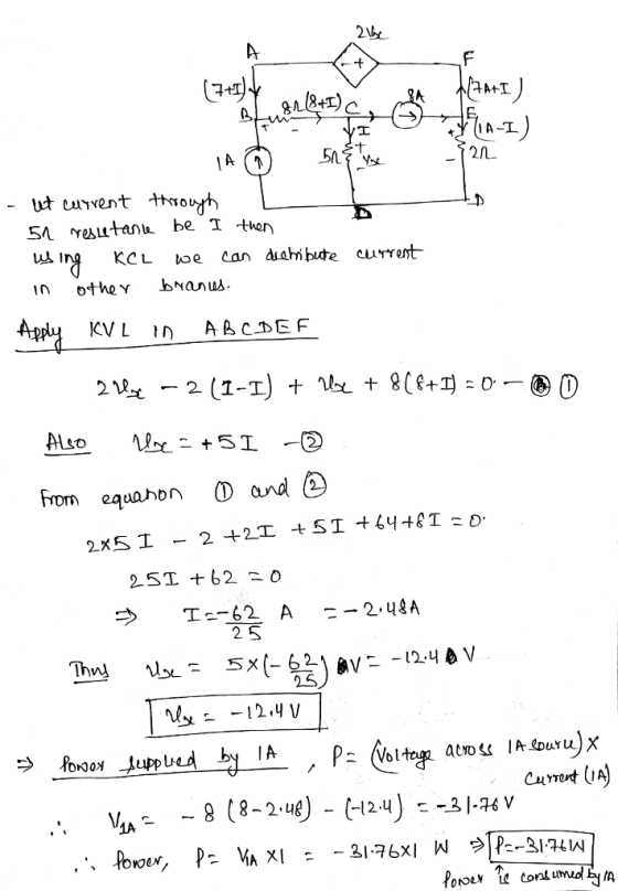
(a) Determine the voltage vz in the circuit shown in Figure 3 and the power supplied...
1. For the circuit shown in figure P-01, determine a. Coupling coefficient of coupled inductors! b. The voltage, Vx as shown in the circuit! C. Energy stored inside the coupled inductors! ML 2Ω Fi...
 1. For the circuit shown in figure P-01, determine a. Coupling coefficient of coupled inductors! b. The voltage, Vx as shown in the circuit! C. Energy stored inside the coupled inductors! ML 2Ω Figure P-01 2. For the ideal transformer circuit shown in figure P-02, determine a. Primary and secondary currents, Ii and I2! b. Primary and secondary voltages, Yi and V2! C. Complex power supplied by the source 1, 2Ω 1:2 6090V ms svo 12Ω Figure P-02
1. For...
1. For the circuit shown in figure P-01, determine a. Coupling coefficient of coupled inductors! b. The voltage, Vx as shown in the circuit! C. Energy stored inside the coupled inductors! ML 2Ω Figure P-01 2. For the ideal transformer circuit shown in figure P-02, determine a. Primary and secondary currents, Ii and I2! b. Primary and secondary voltages, Yi and V2! C. Complex power supplied by the source 1, 2Ω 1:2 6090V ms svo 12Ω Figure P-02
1. For...
Answer # 3,27 PROBLEMS 3.27 Use mesh analysis to determine the amount of power supplied by...
 Answer # 3,27
PROBLEMS 3.27 Use mesh analysis to determine the amount of power supplied by the voltage source in the circuit of Fig. P3.27. 8Ω 9 A 2Ω 4Ω +40 V Figure P3.27: Circuit for Problem 3.27. 28 Determine V in the circuit of Fig. P3.28 using mesh alysis 4Ω 4Ω
Answer # 3,27
PROBLEMS 3.27 Use mesh analysis to determine the amount of power supplied by the voltage source in the circuit of Fig. P3.27. 8Ω 9 A 2Ω 4Ω +40 V Figure P3.27: Circuit for Problem 3.27. 28 Determine V in the circuit of Fig. P3.28 using mesh alysis 4Ω 4Ω
. Use Ohm's law and voltage division to find the power supplied by the source and...
 . Use Ohm's law and voltage division to find the power supplied by the source and power dissipated in 60 and 8Ω resistors. 1.2Ω 4Ω 20 A 2Ω 8Ω 12Ω
2.19 Consider the circuit shown in Figure P2.19. The Zener diode voltage is Vz = 3.9...
 2.19 Consider the circuit shown in Figure P2.19. The Zener diode voltage is Vz = 3.9 V and the Zener diode incremental resistance is ra = 0. (a) Deter- mine Iz, Il, and the power dissipated in the diode. (b) Repeat part (a) if the 4 k 32 load resistor is increased to 10 KS2. 12 k22 " 1112 vz$ 111 462 20 v= Figure P2.19
b) For the circuit shown in Figure Q1(b) below, the voltage source is 18 V. Determine...
 b) For the circuit shown in Figure Q1(b) below, the voltage source is 18 V. Determine Vo, Voz and /. [CO2/PO3/C4] (10 marks) Vo1 0.47 k 1 ka Vo2 Si 18 V Si Figure Q1(b) For the circuit shown in Figure Q1(b) below, the voltage source is 18 V. Determine b) Vot, Voz and / [CO2/PO3/C4] (10 marks) Vof 1 ka 0.47 kn Vo2 ZSI 18 V Figure Q1(b) ) Figure Q1(c) shows a basic voltage regulator circuit. Determine Vi,...
Problem 4 Part A Find the average power supplied by the voltage source in the circuit...
 Problem 4 Part A Find the average power supplied by the voltage source in the circuit in the figure if Ug = 40 cos 10% V. Express your answer with the appropriate units. View Available Hint(s) UNHA to P= 9.69 w Submit Previous Answers Figure 1 of 1 > X Incorrect; Try Again; & attempts remaining Part B 401 Find the reactive power supplied by the voltage source in the circuit. Express your answer with the appropriate units. 80 H...
In the circuit below, the voltage supplied by the power source is 10 V and the...
 In the circuit below, the voltage supplied by the power source
is 10 V and the current flowing through the circuit is 0.12
A.
KE3 Prelaboratory Questions E3 - Question 1: Resistance in a Circuit 1 of 5 Review 1 Constants i Periodic Table Part A In the circuit below, the voltage supplied by the power source is 10 V and the current flowing through the circuit is 0.12 A What is the resistance R2? 35 S2 33.75 Submit Previous...
In the circuit below, the voltage supplied by the power source
is 10 V and the current flowing through the circuit is 0.12
A.
KE3 Prelaboratory Questions E3 - Question 1: Resistance in a Circuit 1 of 5 Review 1 Constants i Periodic Table Part A In the circuit below, the voltage supplied by the power source is 10 V and the current flowing through the circuit is 0.12 A What is the resistance R2? 35 S2 33.75 Submit Previous...
The power supply of the circuit shown in the given figure supplies a voltage A =...
 The power supply of the circuit shown in the given figure supplies a voltage A = 7 V. Compute the current / and the power P that must be supplied 30 kn 80 kn 40 kn The current for the given circuit is 7x10⁴A The power P that must be applied is [ *10-3 w.
7 2Ω 6Ω For the circuit shown, find (a) the voltage Vo, (b) the power delivered...
 7 2Ω 6Ω For the circuit shown, find (a) the voltage Vo, (b) the power delivered to the circuit by the current source; and (c) the power dissipated in the 10Ω resistor. 2) 5A Vo 30n 64Ω
For the circuit shown, the power absorbed or supplied by the independent voltage Source 5 lx...
 For the circuit shown, the power absorbed or supplied by the independent voltage Source 5 lx Vs 60V 200 0.25 Vs 50 } Select one: O a. 360 W (absorbed) b. - 675 W (supply) C. - 1620 W (supply) O d. 2356 W (absorbed) Clear my choice
 1. For the circuit shown in figure P-01, determine a. Coupling coefficient of coupled inductors! b. The voltage, Vx as shown in the circuit! C. Energy stored inside the coupled inductors! ML 2Ω Figure P-01 2. For the ideal transformer circuit shown in figure P-02, determine a. Primary and secondary currents, Ii and I2! b. Primary and secondary voltages, Yi and V2! C. Complex power supplied by the source 1, 2Ω 1:2 6090V ms svo 12Ω Figure P-02
1. For...
1. For the circuit shown in figure P-01, determine a. Coupling coefficient of coupled inductors! b. The voltage, Vx as shown in the circuit! C. Energy stored inside the coupled inductors! ML 2Ω Figure P-01 2. For the ideal transformer circuit shown in figure P-02, determine a. Primary and secondary currents, Ii and I2! b. Primary and secondary voltages, Yi and V2! C. Complex power supplied by the source 1, 2Ω 1:2 6090V ms svo 12Ω Figure P-02
1. For...
 Answer # 3,27
PROBLEMS 3.27 Use mesh analysis to determine the amount of power supplied by the voltage source in the circuit of Fig. P3.27. 8Ω 9 A 2Ω 4Ω +40 V Figure P3.27: Circuit for Problem 3.27. 28 Determine V in the circuit of Fig. P3.28 using mesh alysis 4Ω 4Ω
Answer # 3,27
PROBLEMS 3.27 Use mesh analysis to determine the amount of power supplied by the voltage source in the circuit of Fig. P3.27. 8Ω 9 A 2Ω 4Ω +40 V Figure P3.27: Circuit for Problem 3.27. 28 Determine V in the circuit of Fig. P3.28 using mesh alysis 4Ω 4Ω
 . Use Ohm's law and voltage division to find the power supplied by the source and power dissipated in 60 and 8Ω resistors. 1.2Ω 4Ω 20 A 2Ω 8Ω 12Ω
 2.19 Consider the circuit shown in Figure P2.19. The Zener diode voltage is Vz = 3.9 V and the Zener diode incremental resistance is ra = 0. (a) Deter- mine Iz, Il, and the power dissipated in the diode. (b) Repeat part (a) if the 4 k 32 load resistor is increased to 10 KS2. 12 k22 " 1112 vz$ 111 462 20 v= Figure P2.19
 b) For the circuit shown in Figure Q1(b) below, the voltage source is 18 V. Determine Vo, Voz and /. [CO2/PO3/C4] (10 marks) Vo1 0.47 k 1 ka Vo2 Si 18 V Si Figure Q1(b) For the circuit shown in Figure Q1(b) below, the voltage source is 18 V. Determine b) Vot, Voz and / [CO2/PO3/C4] (10 marks) Vof 1 ka 0.47 kn Vo2 ZSI 18 V Figure Q1(b) ) Figure Q1(c) shows a basic voltage regulator circuit. Determine Vi,...
 Problem 4 Part A Find the average power supplied by the voltage source in the circuit in the figure if Ug = 40 cos 10% V. Express your answer with the appropriate units. View Available Hint(s) UNHA to P= 9.69 w Submit Previous Answers Figure 1 of 1 > X Incorrect; Try Again; & attempts remaining Part B 401 Find the reactive power supplied by the voltage source in the circuit. Express your answer with the appropriate units. 80 H...
 In the circuit below, the voltage supplied by the power source
is 10 V and the current flowing through the circuit is 0.12
A.
KE3 Prelaboratory Questions E3 - Question 1: Resistance in a Circuit 1 of 5 Review 1 Constants i Periodic Table Part A In the circuit below, the voltage supplied by the power source is 10 V and the current flowing through the circuit is 0.12 A What is the resistance R2? 35 S2 33.75 Submit Previous...
In the circuit below, the voltage supplied by the power source
is 10 V and the current flowing through the circuit is 0.12
A.
KE3 Prelaboratory Questions E3 - Question 1: Resistance in a Circuit 1 of 5 Review 1 Constants i Periodic Table Part A In the circuit below, the voltage supplied by the power source is 10 V and the current flowing through the circuit is 0.12 A What is the resistance R2? 35 S2 33.75 Submit Previous...
 The power supply of the circuit shown in the given figure supplies a voltage A = 7 V. Compute the current / and the power P that must be supplied 30 kn 80 kn 40 kn The current for the given circuit is 7x10⁴A The power P that must be applied is [ *10-3 w.
 7 2Ω 6Ω For the circuit shown, find (a) the voltage Vo, (b) the power delivered to the circuit by the current source; and (c) the power dissipated in the 10Ω resistor. 2) 5A Vo 30n 64Ω
 For the circuit shown, the power absorbed or supplied by the independent voltage Source 5 lx Vs 60V 200 0.25 Vs 50 } Select one: O a. 360 W (absorbed) b. - 675 W (supply) C. - 1620 W (supply) O d. 2356 W (absorbed) Clear my choice
Most questions answered within 3 hours.
-
(63
#14)
which of the following statments best describes how chamging
the concentration of the substances...
asked 2 hours ago -
In the following reaction, which element is undergoing
oxidation: Na2SO3 + N2O --> N2 + Na2SO4...
asked 3 hours ago -
Which of the following pairs of ions have the same electron
configuration?
I: Br− and Se2−...
asked 6 hours ago -
The Foremost Composite Materials Company is planning a two-day
sales conference for October 19-20. The conference...
asked 6 hours ago -
3) Illustrate the observed pattern of relatedness of organisms
versus adaptations to specific conditions. This means...
asked 6 hours ago -
In winter a lake has a 0.35 m thick ice layer over 1.10 m of
water....
asked 7 hours ago -
Assuming the following has been encrypted with a Vigenere cipher
below, use the method(s) and assumptions...
asked 8 hours ago -
How would I use switch statements to write a program that will
take an input of...
asked 8 hours ago -
Imagine a reaction in which methane gas combusts at a constant
pressure of 1 atm and...
asked 8 hours ago -
Two parallel wires (each 12 m in length) are separated by a
distance of 0.065 m...
asked 8 hours ago -
Suppose there were three masses at the corner of uniform
equilateral triangle. The masses are m1...
asked 8 hours ago -
Situation: A building that is 618 m above the ground floor. How
many times would a...
asked 8 hours ago