For the source-follower network of Fig. 8.91:a. Determine AvNL, Zi, and Zo.b. Sketch the t...
For the source-follower network of Fig. 8.91:
a. Determine AvNL, Zi, and Zo.
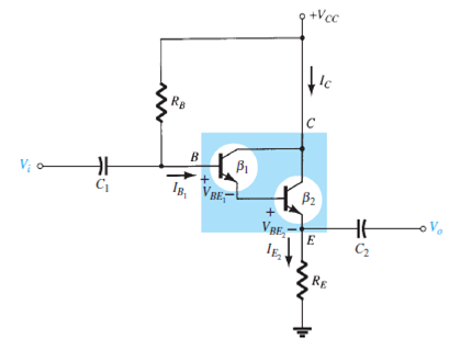
b. Sketch the two-port model of Fig. 5.75 with the parameters determined in part (a) in place.
c. Determine AvL and Avs.
d. Change RL to 4.7 kΩ and calculate AvL and Avs. What was the effect of increasing levels of R L on both voltage gains?
e. Change Rsig to 20 kΩ (with RL at 2.2 kΩ) and calculate AvL and Avs. What was the effect of increasing levels of Rsig on both voltage gains?
f. Change RL to 4.7 kΩ and Rsig to 20 kΩ and calculate Zi and Zo. What was the effect on both impedance parameters?
FIG. 8.91
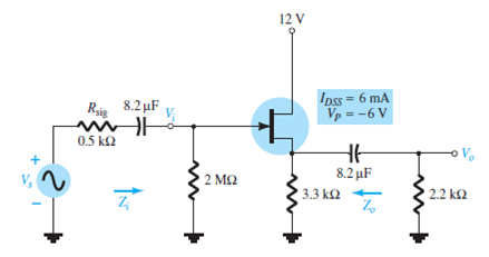
FIG. 5.75 Emitter-follower configuration with a Darlington amplifier.
Step-by-Step Solution
Request Solution!
We need at least 10 more requests to produce the solution.
0 / 10 have requested this problem solution
The more requests, the faster the answer.
Most questions answered within 3 hours.
-
Calculating the space time for parallel reactions. m-Xylene is reacted over a ZSM-5 zeolit...
-
Determine Vo and ID for the networks of Fig. 2.160.FIG. 2.160
-
The truck travels along a circular road that has a radius of 50 m at a speed of 4 m/s. F...
-
A state legislature enacted a statute that required any motorcycle operator or passenger...
-
A 1024 × 1024 8-bit image with 5.3 bits/pixel entropy [computed from its histogram using E...
-
In Problem 3.3, we estimated the equationwhere we now report standard errors along with th...
-
In each of the following cases, deduce the nature of the light that is consistent with the...
-
Solve Example 20.5 such that the x, y, z axes move with curvilinear translation, Ω = 0 in...
-
In Fig. 6.43, if i = cos 4t and v = sin 4t, the element is:(a)a resistor(b) a capacitor(c)...
-
Sketch vo for each network of Fig. 2.181 for the input shown.FIG. 2.181
-
(Supplement B) Computing and Reporting Cash Flow Effectsof Sale of Plant and EquipmentDuri...
-
A 350-mL spherical flask contains 0.075 mol of an ideal gas at a temperature of 293 K. Wha...