Given the circuit on the diagram below with R1 = 6 kΩ, R2 = 13 kΩ,...
Given the circuit on the diagram below with R1 = 6 kΩ, R2 = 13 kΩ, R3 = 11 kΩ and R4 = 9 kΩ.
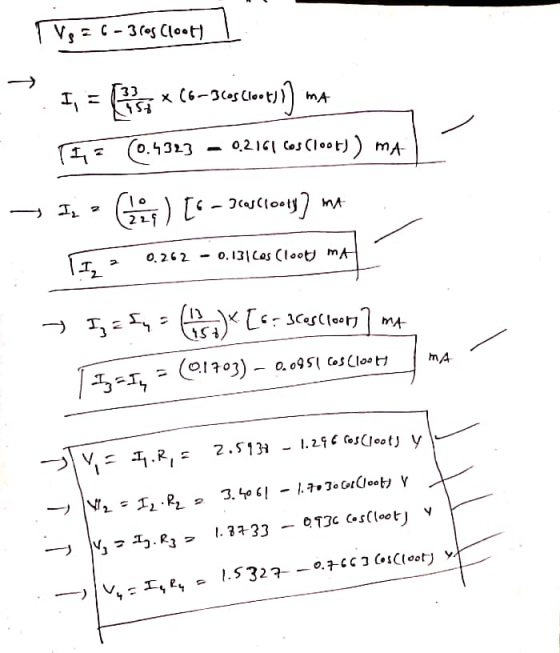
Using current and voltage division, find I1, I2, I3, and I4 , and also the voltages across the resistors (V1, V2, V3, and V4) when:
Vs= 6 − 3cos100t V

Homework Answers
Answer question
![тіл RECK 3R₂ = 13ka 3 {Rua åka çztif VI on applying kcl ar houk © =) | 10=0] R₃tru GK = 0.5676 Vs 5x + 13k + RAIK Tv = 0.5676](http://img.homeworklib.com/questions/c8c30500-3919-11eb-928f-cb05d078d64b.png?x-oss-process=image/resize,w_560)
Add Answer to:
Given the circuit on the diagram below with R1 = 6 kΩ, R2 = 13
kΩ,...
A circuit is constructed with six resistors and two batteries asshown. The battery voltages are...
A circuit is constructed with six resistors and two batteries as shown. The battery voltages are V1 = 18 V and V2 = 12 V. The positive terminals are indicated with a + sign, The values for the resistors are: R1 = R5 = 55 ?, R2 = R6 = 148 ? R3 = 84 ?, and R4 = 76 ?. The positive directions for the currents I1, I2 and I3 are indicated by the directions of the arrows.1)What is...
1)What is the output voltage V0 if op-amp is ideal? R1= 2 KΩ, R2=8 KΩ, R3=3.2...
 1)What is the output
voltage V0 if op-amp is ideal?
R1= 2 KΩ, R2=8 KΩ, R3=3.2 KΩ, R4=6 KΩ, R5=19
KΩ, R6=4.6 KΩ, RL=9.6 KΩ, V1=1V, I2=0.5 mA and V3=2.5 V.
2) for the same circuit, R1= 2 KΩ R2=8
KΩ, R3=3.6 KΩ, R4=6 KΩ, R5=16.9 KΩ, R6=15 KΩ, RL=10 KΩ, V1=1V,
I2=0.5mA and V3=2V. What is the input impedance as
seen by source V3?
+ | R1 ہی ہے۔ ۸۸۸ ة -(1+ R5 | + ابرها -
1)What is the output
voltage V0 if op-amp is ideal?
R1= 2 KΩ, R2=8 KΩ, R3=3.2 KΩ, R4=6 KΩ, R5=19
KΩ, R6=4.6 KΩ, RL=9.6 KΩ, V1=1V, I2=0.5 mA and V3=2.5 V.
2) for the same circuit, R1= 2 KΩ R2=8
KΩ, R3=3.6 KΩ, R4=6 KΩ, R5=16.9 KΩ, R6=15 KΩ, RL=10 KΩ, V1=1V,
I2=0.5mA and V3=2V. What is the input impedance as
seen by source V3?
+ | R1 ہی ہے۔ ۸۸۸ ة -(1+ R5 | + ابرها -
A circuit consists of a power supply and two resistors R1 and R2 connected in parallel....
A circuit consists of a power supply and two resistors R1 and R2 connected in parallel. The resistance of R1 is higher than the resistance of R2 (R1 > R2) Which of the following is correct? Select one: a. The current through R1 is the same as the current through R2 (I1 = I2 ?) The voltage across R1 is the same as the voltage across R2 (V1 = V2 ?) b. The current through R1 is the same as...
Hi I need help with answers 11-15. thank you The next three questions are about this...
 Hi I need help with answers 11-15. thank you
The next three questions are about this circuit. The voltage of
the battery is 12 V, and the values of the resistances are:
R1 = 5 ohms, R2 = 10 ohms, R3 = 15
ohms, and R4 = 20 ohms.
The next three questions pertain to the following situation.
11) R1 and R4
are in:
parallel
series
neither
12) Compare the magnitude of the
voltage across R2 and R4
V2 > V4
V2...
Hi I need help with answers 11-15. thank you
The next three questions are about this circuit. The voltage of
the battery is 12 V, and the values of the resistances are:
R1 = 5 ohms, R2 = 10 ohms, R3 = 15
ohms, and R4 = 20 ohms.
The next three questions pertain to the following situation.
11) R1 and R4
are in:
parallel
series
neither
12) Compare the magnitude of the
voltage across R2 and R4
V2 > V4
V2...
1. For the circuit shown, the following is known: R1 = 82, R3 = 1.2, v2...
 1. For the circuit shown, the following is known: R1 = 82, R3 = 1.2, v2 = -10 V, and i3 = 2 A. Determine the unknown voltages and currents (V1, V3, i1, and i2) as well as R2. R2 02 12 V iztiz R3 a 03 R1 U 1 10 V +
A circuit is constructed with six resistors and two batteries as shown The battery voltages are V1=18 V and V2=12 V.
 A circuit is constructed with six resistors and two batteries as shown The battery voltages are V1=18 V and V2=12 V. The positive terminals are indicated with a + sign, The values for the resistors are: R1=R5=66 Ω, R2=R6=83 Ω R3=55 Ω, and R4=69 Ω. The positive directions for the currents I1, I2 and I3 are indicated by the directions of the arrows.1) What is V4, the magnitude of the voltage across the resistor R4? 2) What is I3, the current...
How much current flows through each of the four resistors?
 Consider the circuit shown in the diagram below. The battery has
a voltage V=12.0 V and the resistors have the following values.R1= 3.89 Ω ; R2= 7.78 Ω ; R3= 19.45 Ω ; R4= 11.67 ΩHow much current flows through each of the four resistors?I1 =I2 =I3 =I4 =
Consider the circuit shown in the diagram below. The battery has
a voltage V=12.0 V and the resistors have the following values.R1= 3.89 Ω ; R2= 7.78 Ω ; R3= 19.45 Ω ; R4= 11.67 ΩHow much current flows through each of the four resistors?I1 =I2 =I3 =I4 =
Find the potential difference across each resistor in the figure below. (R1 = 4.60 ?, R2...
 Find the potential difference
across each resistor in the figure below. (R1 =
4.60 ?, R2 = 4.20 ?, R3 =
2.80 ?, R4 = 1.80 ?)??
?V1
=
?V2
=
?V3
=
?V4
=
12.0 V 8.00 V 18.0 V
Find the potential difference
across each resistor in the figure below. (R1 =
4.60 ?, R2 = 4.20 ?, R3 =
2.80 ?, R4 = 1.80 ?)??
?V1
=
?V2
=
?V3
=
?V4
=
12.0 V 8.00 V 18.0 V
In the circuit below v1 = 45 V, v2 = -60 V, v3 = 15 V, R1 = 6.3 kΩ, and R2 = 4.9 kΩ.
In the circuit below v1 = 45 V, v2 = -60 V, v3 = 15 V, R1 = 6.3 kΩ, and R2 = 4.9 kΩ.Transform the left two practical voltage sources in the circuit below into practical current sources. Combine resistors and ideal current sources and then transform the resultant practical current source into a practical voltage source. Finally, combine the ideal voltage sources.(a) If RL = 7.4 kΩ, find the power delivered to it.(b) What is the maximum power...
Consider the circuit shown in the figure(Figure 1). Suppose thefour resistors in this circuit have...
 Consider the circuit shown in the figure(Figure 1). Suppose the
four resistors in this circuit have the values R1 = 13 Ω , R2 = 7.2
Ω , R3 = 6.2 Ω , and R4= 13 Ω , and that the emf of the battery is
E = 18 V .Part AFind the current through each resistor using the rules for
series and parallel resistors. Express your answers using two
significant figures separated by commas.I1,I2,I3,I4=______APart BFind the current through each...
Consider the circuit shown in the figure(Figure 1). Suppose the
four resistors in this circuit have the values R1 = 13 Ω , R2 = 7.2
Ω , R3 = 6.2 Ω , and R4= 13 Ω , and that the emf of the battery is
E = 18 V .Part AFind the current through each resistor using the rules for
series and parallel resistors. Express your answers using two
significant figures separated by commas.I1,I2,I3,I4=______APart BFind the current through each...
 1)What is the output
voltage V0 if op-amp is ideal?
R1= 2 KΩ, R2=8 KΩ, R3=3.2 KΩ, R4=6 KΩ, R5=19
KΩ, R6=4.6 KΩ, RL=9.6 KΩ, V1=1V, I2=0.5 mA and V3=2.5 V.
2) for the same circuit, R1= 2 KΩ R2=8
KΩ, R3=3.6 KΩ, R4=6 KΩ, R5=16.9 KΩ, R6=15 KΩ, RL=10 KΩ, V1=1V,
I2=0.5mA and V3=2V. What is the input impedance as
seen by source V3?
+ | R1 ہی ہے۔ ۸۸۸ ة -(1+ R5 | + ابرها -
1)What is the output
voltage V0 if op-amp is ideal?
R1= 2 KΩ, R2=8 KΩ, R3=3.2 KΩ, R4=6 KΩ, R5=19
KΩ, R6=4.6 KΩ, RL=9.6 KΩ, V1=1V, I2=0.5 mA and V3=2.5 V.
2) for the same circuit, R1= 2 KΩ R2=8
KΩ, R3=3.6 KΩ, R4=6 KΩ, R5=16.9 KΩ, R6=15 KΩ, RL=10 KΩ, V1=1V,
I2=0.5mA and V3=2V. What is the input impedance as
seen by source V3?
+ | R1 ہی ہے۔ ۸۸۸ ة -(1+ R5 | + ابرها -
 Hi I need help with answers 11-15. thank you
The next three questions are about this circuit. The voltage of
the battery is 12 V, and the values of the resistances are:
R1 = 5 ohms, R2 = 10 ohms, R3 = 15
ohms, and R4 = 20 ohms.
The next three questions pertain to the following situation.
11) R1 and R4
are in:
parallel
series
neither
12) Compare the magnitude of the
voltage across R2 and R4
V2 > V4
V2...
Hi I need help with answers 11-15. thank you
The next three questions are about this circuit. The voltage of
the battery is 12 V, and the values of the resistances are:
R1 = 5 ohms, R2 = 10 ohms, R3 = 15
ohms, and R4 = 20 ohms.
The next three questions pertain to the following situation.
11) R1 and R4
are in:
parallel
series
neither
12) Compare the magnitude of the
voltage across R2 and R4
V2 > V4
V2...
 1. For the circuit shown, the following is known: R1 = 82, R3 = 1.2, v2 = -10 V, and i3 = 2 A. Determine the unknown voltages and currents (V1, V3, i1, and i2) as well as R2. R2 02 12 V iztiz R3 a 03 R1 U 1 10 V +
 Consider the circuit shown in the diagram below. The battery has
a voltage V=12.0 V and the resistors have the following values.R1= 3.89 Ω ; R2= 7.78 Ω ; R3= 19.45 Ω ; R4= 11.67 ΩHow much current flows through each of the four resistors?I1 =I2 =I3 =I4 =
Consider the circuit shown in the diagram below. The battery has
a voltage V=12.0 V and the resistors have the following values.R1= 3.89 Ω ; R2= 7.78 Ω ; R3= 19.45 Ω ; R4= 11.67 ΩHow much current flows through each of the four resistors?I1 =I2 =I3 =I4 =
 Find the potential difference
across each resistor in the figure below. (R1 =
4.60 ?, R2 = 4.20 ?, R3 =
2.80 ?, R4 = 1.80 ?)??
?V1
=
?V2
=
?V3
=
?V4
=
12.0 V 8.00 V 18.0 V
Find the potential difference
across each resistor in the figure below. (R1 =
4.60 ?, R2 = 4.20 ?, R3 =
2.80 ?, R4 = 1.80 ?)??
?V1
=
?V2
=
?V3
=
?V4
=
12.0 V 8.00 V 18.0 V
 Consider the circuit shown in the figure(Figure 1). Suppose the
four resistors in this circuit have the values R1 = 13 Ω , R2 = 7.2
Ω , R3 = 6.2 Ω , and R4= 13 Ω , and that the emf of the battery is
E = 18 V .Part AFind the current through each resistor using the rules for
series and parallel resistors. Express your answers using two
significant figures separated by commas.I1,I2,I3,I4=______APart BFind the current through each...
Consider the circuit shown in the figure(Figure 1). Suppose the
four resistors in this circuit have the values R1 = 13 Ω , R2 = 7.2
Ω , R3 = 6.2 Ω , and R4= 13 Ω , and that the emf of the battery is
E = 18 V .Part AFind the current through each resistor using the rules for
series and parallel resistors. Express your answers using two
significant figures separated by commas.I1,I2,I3,I4=______APart BFind the current through each...
Most questions answered within 3 hours.
-
The blues made its way into many kinds of music. Eric Clapton,
The Beatles, and Elvis...
asked 1 hour ago -
8. A wave in a string has a wave function given by: y (x, t) =...
asked 20 minutes ago -
If you’re standing at the bottom of a hill and asked to evaluate
it while being...
asked 2 hours ago -
1. Which region has taken the lead in the world of
e-waste handling?
a) European Union...
asked 2 hours ago -
A 8.15- g bullet from a 9-mm pistol has a velocity of 366.0 m/s.
It strikes...
asked 3 hours ago -
The outstanding bonds of Alpha Extracts have a yield to maturity
of 7.4 percent and a...
asked 3 hours ago -
The Problem: The Case of the Harmonizing Vacations
Your CEO is exploring partnering with a European...
asked 4 hours ago -
A chemical equation is balanced by adding coefficients in front
of some formulas so that the...
asked 4 hours ago -
From the literature (reference your sources): What are the
lattice parameters of calcite and aragonite? Why...
asked 5 hours ago -
Your system is rejecting the question am asking which is
preceded by a case study. It...
asked 5 hours ago -
3. On January 2, 2000, Larry creates a trust with himself as
trustee. Larry as trustee...
asked 5 hours ago -
A member of the volleyball team spikes the ball. During this
process, she changes the velocity...
asked 5 hours ago