The solid 30-mm-diameter shaft is used to transmit the torques applied to the gears Determine the...
The solid 30-mm-diameter shaft is used to transmit the torques applied to the gears
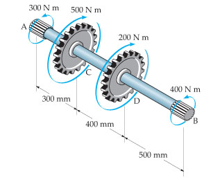
Determine the absolute maximum shear stress on the shaft.
Express your answer to three significant figures and include the appropriate units.
Homework Answers

Add Answer to:
The solid 30-mm-diameter shaft is used to transmit the torques applied to the gears Determine the...
The solid 30-mm-diameter shaft is used to transmit the torques applied to the gears.
 The solid 30-mm-diameter shaft is used to transmit the torques applied to the gears. Determine the absolute maximum shear stress in the shaft.
2. The solid 50-mm-diameter shaft is used to transmit the torques applied to the gears as...
 2. The solid 50-mm-diameter shaft is used to transmit the torques applied to the gears as shown in Figure 5. Determine the absolute maximum shear stress in the shaft. (15 marks)
The solid 35-mm-diameter shaft is used to transmit the torques applied to the gears. Determine the...
 The solid 35-mm-diameter shaft is used to transmit the torques applied to the gears. Determine the absolute maximum shear stress in the shaft 2. 300 Nm 500 N mm 200 N m 400 N m 300 mm 400 mm 500 mm
Part A The solid aluminum shaft has a diameter of 60 mm. Set 1-2030 N.m. (Figure...
 Part A The solid aluminum shaft has a diameter of 60 mm. Set 1-2030 N.m. (Figure 1) Determine the absolute maximum shear stress in the shaft. Express your answer to three significant figures and include appropriate units. (Tabs )maxValue Units Figure 1 of 1 Submit Request Answer Provide Feedback 300 Nm 600 Nmノ 900 N m
The solid steel shaft DF has a diameter of 25 mm and is supported by smooth...
 The solid steel shaft DF has a diameter of 25 mm and is supported by smooth bearings at D and E. It is coupled to a motor at F, which delivers 12 kW of power to the shaft while it is turning at 60 rev/s.The gears A, B, and C remove 3 kW, 4 kW, and 5 kW respectively. The shaft is free to turn in its support bearings D and E. (Figure 1) Part A Determine the absolute maximum...
The solid steel shaft DF has a diameter of 25 mm and is supported by smooth...
 The solid steel shaft DF has a diameter of 25 mm and is supported by smooth bearings at D and E. It is coupled to a motor at F, which delivers 12 kW of power to the shaft while it is turning at 35 rev/s . The gears A B, and C remove 3 kW, 4 kW, and 5 kW respectively The shaft is free to turn in its support bearings D and E (Figure 1) Part A Determine the...
The splined ends and gears attached to the A992 steel shaft are subjected to the torques...
 The splined ends and gears attached to the A992 steel shaft are subjected to the torques shown. If the shaft has a diameter of 40 mm. [10 marks) a-Draw the torque diagram. [2 marks] b-Determine the angle of twist of end B with respect to end A. [3 marks] C- Determine the maximum shear stress the shaft is subjected to. [2 marks] d- If the allowable shear stress in the shaft is 300 MPa, and the allowable angle of twist...
The splined ends and gears attached to the A992 steel shaft are subjected to the torques...
 The splined ends and gears attached to the A992 steel shaft are subjected to the torques shown. If the shaft has a diameter of 40 mm. [10 marks] a-Draw the torque diagram. [2 marks] b-Determine the angle of twist of end B with respect to end A. [3 marks] C- Determine the maximum shear stress the shaft is subjected to. [2 marks] d- If the allowable shear stress in the shaft is 300 MPa, and the allowable angle of twist...
Torsional Deformation of a Circular Shaft Learning Goal: To calculate torsional deformation and s...
 Torsional Deformation of a Circular Shaft Learning Goal: To calculate torsional deformation and shear stress due to an applied force in a door handle design. A locked door handle is composed of a solid orcular shaft AB with a diameter of b 101 mm and a flat plate BC with a ferce P-65 N applied at point C as shown Let c 523 mm,d 135 mm, and e 157 mm (Treat the hande as if it were a cantilever beam)...
Learning Goal: To calculate torsional deformation and shear stress due to an applied force in a...
 Learning Goal: To calculate torsional deformation and shear stress due to an applied force in a door handle design. A locked door handle is composed of a solid circular shaft AB with a diameter fb = 105 mm and a flat plate BC with a force P = 76 N applied at point C as shown. Let c = 543 mm, d = 125 mm, and e = 145 mm. (Treat the handle as if it were a cantilever beam.)...
 2. The solid 50-mm-diameter shaft is used to transmit the torques applied to the gears as shown in Figure 5. Determine the absolute maximum shear stress in the shaft. (15 marks)
 The solid 35-mm-diameter shaft is used to transmit the torques applied to the gears. Determine the absolute maximum shear stress in the shaft 2. 300 Nm 500 N mm 200 N m 400 N m 300 mm 400 mm 500 mm
 Part A The solid aluminum shaft has a diameter of 60 mm. Set 1-2030 N.m. (Figure 1) Determine the absolute maximum shear stress in the shaft. Express your answer to three significant figures and include appropriate units. (Tabs )maxValue Units Figure 1 of 1 Submit Request Answer Provide Feedback 300 Nm 600 Nmノ 900 N m
 The solid steel shaft DF has a diameter of 25 mm and is supported by smooth bearings at D and E. It is coupled to a motor at F, which delivers 12 kW of power to the shaft while it is turning at 60 rev/s.The gears A, B, and C remove 3 kW, 4 kW, and 5 kW respectively. The shaft is free to turn in its support bearings D and E. (Figure 1) Part A Determine the absolute maximum...
 The solid steel shaft DF has a diameter of 25 mm and is supported by smooth bearings at D and E. It is coupled to a motor at F, which delivers 12 kW of power to the shaft while it is turning at 35 rev/s . The gears A B, and C remove 3 kW, 4 kW, and 5 kW respectively The shaft is free to turn in its support bearings D and E (Figure 1) Part A Determine the...
 The splined ends and gears attached to the A992 steel shaft are subjected to the torques shown. If the shaft has a diameter of 40 mm. [10 marks) a-Draw the torque diagram. [2 marks] b-Determine the angle of twist of end B with respect to end A. [3 marks] C- Determine the maximum shear stress the shaft is subjected to. [2 marks] d- If the allowable shear stress in the shaft is 300 MPa, and the allowable angle of twist...
 The splined ends and gears attached to the A992 steel shaft are subjected to the torques shown. If the shaft has a diameter of 40 mm. [10 marks] a-Draw the torque diagram. [2 marks] b-Determine the angle of twist of end B with respect to end A. [3 marks] C- Determine the maximum shear stress the shaft is subjected to. [2 marks] d- If the allowable shear stress in the shaft is 300 MPa, and the allowable angle of twist...
 Torsional Deformation of a Circular Shaft Learning Goal: To calculate torsional deformation and shear stress due to an applied force in a door handle design. A locked door handle is composed of a solid orcular shaft AB with a diameter of b 101 mm and a flat plate BC with a ferce P-65 N applied at point C as shown Let c 523 mm,d 135 mm, and e 157 mm (Treat the hande as if it were a cantilever beam)...
 Learning Goal: To calculate torsional deformation and shear stress due to an applied force in a door handle design. A locked door handle is composed of a solid circular shaft AB with a diameter fb = 105 mm and a flat plate BC with a force P = 76 N applied at point C as shown. Let c = 543 mm, d = 125 mm, and e = 145 mm. (Treat the handle as if it were a cantilever beam.)...
Most questions answered within 3 hours.
-
Ammonia will decompose into nitrogen and hydrogen at high
temperature. An industrial chemist studying this reaction...
asked 21 seconds ago -
10. Complete the table below
only using hexadecimal numbers:
AL CODE
EBX
EAX
[EAX]
mov eax,...
asked 18 minutes ago -
trust is best established through the combination of ------and
------- .
1. magnanimity and justice
2....
asked 32 minutes ago -
Blood pressure is normally taken on the upper arm at the level
of the heart. Suppose,...
asked 31 minutes ago -
Suppose that the satellite around the earth has an orbit that is
24 KM larger in...
asked 35 minutes ago -
Calculate the [OH (aq)] in limes which have a [H3O*(aq)] of 1.3 x
10 mol/L
asked 33 minutes ago -
A nozzle with a radius of 0.250 cm is attached to a garden hose
with a...
asked 44 minutes ago -
PLEASE do not use any loops for the program; only recursion is
allowed
4. Write a...
asked 53 minutes ago -
Please help me with me. I did the first part to write the operations but in...
asked 50 minutes ago -
Use Cryptool to find the Cryptographic SHA-1 hash value of the
string "abc". The calculator is...
asked 54 minutes ago -
You are attempting to calculate a firm’s free cash flow to
equity. You know the following...
asked 1 hour ago -
the following reaction occurs in a balloon containing
N2O2 gas
N2O4(g)=2NO2(g)
will the volume of the...
asked 2 hours ago