
Homework Answers

Add Answer to:
6. (15) Given the 1-bit ALU diagram, complete the truth table for the 1-bit ALU with...
1. Complete the TABLE 1 truth tables on the answer sheet for a one-bit ALU that...
 1. Complete the TABLE 1 truth tables on the answer sheet for a one-bit ALU that has 6 inputs: Two operands A0 and BO, Cln0 (the carry-in), control bits F2 FI FO (so, 011 is ADD which means F2 = 0, F1 = 1 FO = 1). The two outputs are: CO (the results of adding/anding/oring two binary digits) and COut0 (the carry out from adding the two binary digits)
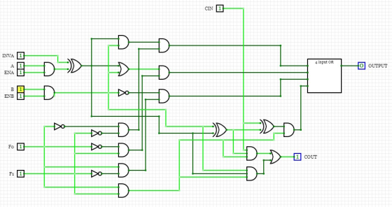
Assume an 8-bit ALU is created from 1-bit ALUS like the one shown below. Logical unit Carry in AB INVA- A+B A Output...
 Assume an 8-bit ALU is created from 1-bit ALUS like the one shown below. Logical unit Carry in AB INVA- A+B A Output ENA- B ENB Sum Enable- lines Fo Full adder Fi Decoder Carry out What operation/output is produced by the inputs FO F1 ENA ENB INVA INC-111100 (where INC is the Carry In for the first stage.)
Assume an 8-bit ALU is created from 1-bit ALUS like the one shown below. Logical unit Carry in AB INVA- A+B...
Assume an 8-bit ALU is created from 1-bit ALUS like the one shown below. Logical unit Carry in AB INVA- A+B A Output ENA- B ENB Sum Enable- lines Fo Full adder Fi Decoder Carry out What operation/output is produced by the inputs FO F1 ENA ENB INVA INC-111100 (where INC is the Carry In for the first stage.)
Assume an 8-bit ALU is created from 1-bit ALUS like the one shown below. Logical unit Carry in AB INVA- A+B...
DO bit 0 1 Q-2 (25p): Assume that logical addresses are 16-bit long: 3 bits for...
 DO bit 0 1 Q-2 (25p): Assume that logical addresses are 16-bit long: 3 bits for segment no and 13 bits for offset. Segment table of the currently running process is given below: a) (5) How many segments can this Segment Present Modify process have at maximum? Length bit Base 0 0 0 0100 0111 0000 0100 0000 1000 0100 b) (15) Convert the following logical 1 1 0100 0100 0001 0010 0010 1100 1000 address to physical (real) address...
Using Structural Modeling in VHDL write the code for: An Arithmetic Logic Unit (ALU) shown in...
 Using Structural Modeling in VHDL write the
code for:
An Arithmetic Logic Unit (ALU) shown in the
figure below. A (16-bit), B
(16-bit), Opcode (3-bit), and
Mode (1-bit) are the inputs; and
ALUOut (16-bit) and Cout (1-bit) are the outputs
of the design. A and B hold the values of the operands. Mode and
Opcode together indicate the type of the operation performed by
ALU.
The ALU components ARE:
-Arithmetic Unit that consists of one 16-bit
adder, 16-bit subtractor, 16-bit...
Using Structural Modeling in VHDL write the
code for:
An Arithmetic Logic Unit (ALU) shown in the
figure below. A (16-bit), B
(16-bit), Opcode (3-bit), and
Mode (1-bit) are the inputs; and
ALUOut (16-bit) and Cout (1-bit) are the outputs
of the design. A and B hold the values of the operands. Mode and
Opcode together indicate the type of the operation performed by
ALU.
The ALU components ARE:
-Arithmetic Unit that consists of one 16-bit
adder, 16-bit subtractor, 16-bit...
Given the Function F1(w, x, y, z) and F2(x0, x1, y0, y1), write the truth table...
 Given the Function F1(w, x, y, z) and F2(x0, x1, y0, y1), write
the truth table for each function. F1(w, x, y, z) - Specified by
the lab instructor F2(x0, x1, y0, y1) is a two bit adder. The
function F2(x0, x1, y0, y1) has 3 outputs - 2 bits for the sum and
1 bit for the carry out Cout
3. Given the Function F1(w, x, y, z) and F2(x0, X1, yo, yı), write the truth table for each...
Given the Function F1(w, x, y, z) and F2(x0, x1, y0, y1), write
the truth table for each function. F1(w, x, y, z) - Specified by
the lab instructor F2(x0, x1, y0, y1) is a two bit adder. The
function F2(x0, x1, y0, y1) has 3 outputs - 2 bits for the sum and
1 bit for the carry out Cout
3. Given the Function F1(w, x, y, z) and F2(x0, X1, yo, yı), write the truth table for each...
Design a circuit with three inputs (A, B, C) and two outputs (F1, F2). The first...
 Design a circuit with three inputs (A, B, C) and two outputs (F1, F2). The first output F1 is 1 when the binary input is 2, 3, 4, 7, otherwise the first output F1 is logic 0. The second output F2 is 1 when the input variables have more l's than 0's. The output is 0 otherwise. Input/ Output ABC F1 F2 000 001 010 011 100 101 a. Derive the truth-table for F1 and F2 as a function of...
Q2. Design a 8-bit ALU (Arithmetic Logic Unit) supporting the following instructions, Z and C values...
 Q2. Design a 8-bit ALU (Arithmetic Logic Unit) supporting the following instructions, Z and C values should be re-evaluated (updated) ifY changes Instruction type code[2:0] operations Logical Status update 001 010 011 100 101 110 ( Bitwise AND) Y = A & B: | Z (C is always 0) (bitwise OR) Y- A B; (bitwise XOR) Y-A B Z (Cis always 0) (negation) Y =-A; (Addition) Y A + B: (subtraction) Y = A-B: (Increment) Y-A+1 (decrement) Y-A-1 Z (C...
Design a circuit with three inputs (A, B, C) and two outputs (F1, F2). The first...
 Design a circuit with three inputs (A, B, C) and two outputs (F1, F2). The first output F1 is logic 1 if the number of l’s in the binary number is less than the number of O's, otherwise F1 is logic 0. The second output F2 is 1 if the binary input is 2, 4, 5, 6,7 otherwise the second output F2 is logic 0. a. Derive the truth-table for F1 and F2 as a function of the 3 inputs....
Finite state machine (FSM) counter design: Gray codes have a useful property in that consecutive numbers differ in only a single bit position. Table 1 lists a 3-bit modulo 8 Gray code representing the...
 Finite state machine (FSM) counter design: Gray
codes have a useful property in that consecutive numbers differ in
only a single bit position. Table 1 lists a 3-bit modulo 8 Gray
code representing the numbers 0 to 7. Design a 3-bit modulo 8 Gray
code counter FSM.
a) First design and sketch a 3-bit modulo 8 Gray code counter
FSM with no inputs and three outputs, the 3-bit signal
Q2:0. (A modulo N counter counts from 0 to N −...
Finite state machine (FSM) counter design: Gray
codes have a useful property in that consecutive numbers differ in
only a single bit position. Table 1 lists a 3-bit modulo 8 Gray
code representing the numbers 0 to 7. Design a 3-bit modulo 8 Gray
code counter FSM.
a) First design and sketch a 3-bit modulo 8 Gray code counter
FSM with no inputs and three outputs, the 3-bit signal
Q2:0. (A modulo N counter counts from 0 to N −...
PROBLEM STATEMENT The mini-calculator will use a small ALU to perform arithmetic operations on two 4-bit values which are set using switches. The ALU operations described below are implemented with a...
 PROBLEM STATEMENT The mini-calculator will use a small ALU to perform arithmetic operations on two 4-bit values which are set using switches. The ALU operations described below are implemented with an Adder/Subtractor component. A pushbutton input allows the current arithmetic result to be saved. An upgraded mini-calculator allows the saved value to be used in place of B as one of the operands. The small ALU that you will design will use the 4-bit adder myadder4 to do several possible...
 1. Complete the TABLE 1 truth tables on the answer sheet for a one-bit ALU that has 6 inputs: Two operands A0 and BO, Cln0 (the carry-in), control bits F2 FI FO (so, 011 is ADD which means F2 = 0, F1 = 1 FO = 1). The two outputs are: CO (the results of adding/anding/oring two binary digits) and COut0 (the carry out from adding the two binary digits)
 Assume an 8-bit ALU is created from 1-bit ALUS like the one shown below. Logical unit Carry in AB INVA- A+B A Output ENA- B ENB Sum Enable- lines Fo Full adder Fi Decoder Carry out What operation/output is produced by the inputs FO F1 ENA ENB INVA INC-111100 (where INC is the Carry In for the first stage.)
Assume an 8-bit ALU is created from 1-bit ALUS like the one shown below. Logical unit Carry in AB INVA- A+B...
Assume an 8-bit ALU is created from 1-bit ALUS like the one shown below. Logical unit Carry in AB INVA- A+B A Output ENA- B ENB Sum Enable- lines Fo Full adder Fi Decoder Carry out What operation/output is produced by the inputs FO F1 ENA ENB INVA INC-111100 (where INC is the Carry In for the first stage.)
Assume an 8-bit ALU is created from 1-bit ALUS like the one shown below. Logical unit Carry in AB INVA- A+B...
 DO bit 0 1 Q-2 (25p): Assume that logical addresses are 16-bit long: 3 bits for segment no and 13 bits for offset. Segment table of the currently running process is given below: a) (5) How many segments can this Segment Present Modify process have at maximum? Length bit Base 0 0 0 0100 0111 0000 0100 0000 1000 0100 b) (15) Convert the following logical 1 1 0100 0100 0001 0010 0010 1100 1000 address to physical (real) address...
 Using Structural Modeling in VHDL write the
code for:
An Arithmetic Logic Unit (ALU) shown in the
figure below. A (16-bit), B
(16-bit), Opcode (3-bit), and
Mode (1-bit) are the inputs; and
ALUOut (16-bit) and Cout (1-bit) are the outputs
of the design. A and B hold the values of the operands. Mode and
Opcode together indicate the type of the operation performed by
ALU.
The ALU components ARE:
-Arithmetic Unit that consists of one 16-bit
adder, 16-bit subtractor, 16-bit...
Using Structural Modeling in VHDL write the
code for:
An Arithmetic Logic Unit (ALU) shown in the
figure below. A (16-bit), B
(16-bit), Opcode (3-bit), and
Mode (1-bit) are the inputs; and
ALUOut (16-bit) and Cout (1-bit) are the outputs
of the design. A and B hold the values of the operands. Mode and
Opcode together indicate the type of the operation performed by
ALU.
The ALU components ARE:
-Arithmetic Unit that consists of one 16-bit
adder, 16-bit subtractor, 16-bit...
 Given the Function F1(w, x, y, z) and F2(x0, x1, y0, y1), write
the truth table for each function. F1(w, x, y, z) - Specified by
the lab instructor F2(x0, x1, y0, y1) is a two bit adder. The
function F2(x0, x1, y0, y1) has 3 outputs - 2 bits for the sum and
1 bit for the carry out Cout
3. Given the Function F1(w, x, y, z) and F2(x0, X1, yo, yı), write the truth table for each...
Given the Function F1(w, x, y, z) and F2(x0, x1, y0, y1), write
the truth table for each function. F1(w, x, y, z) - Specified by
the lab instructor F2(x0, x1, y0, y1) is a two bit adder. The
function F2(x0, x1, y0, y1) has 3 outputs - 2 bits for the sum and
1 bit for the carry out Cout
3. Given the Function F1(w, x, y, z) and F2(x0, X1, yo, yı), write the truth table for each...
 Design a circuit with three inputs (A, B, C) and two outputs (F1, F2). The first output F1 is 1 when the binary input is 2, 3, 4, 7, otherwise the first output F1 is logic 0. The second output F2 is 1 when the input variables have more l's than 0's. The output is 0 otherwise. Input/ Output ABC F1 F2 000 001 010 011 100 101 a. Derive the truth-table for F1 and F2 as a function of...
 Q2. Design a 8-bit ALU (Arithmetic Logic Unit) supporting the following instructions, Z and C values should be re-evaluated (updated) ifY changes Instruction type code[2:0] operations Logical Status update 001 010 011 100 101 110 ( Bitwise AND) Y = A & B: | Z (C is always 0) (bitwise OR) Y- A B; (bitwise XOR) Y-A B Z (Cis always 0) (negation) Y =-A; (Addition) Y A + B: (subtraction) Y = A-B: (Increment) Y-A+1 (decrement) Y-A-1 Z (C...
 Design a circuit with three inputs (A, B, C) and two outputs (F1, F2). The first output F1 is logic 1 if the number of l’s in the binary number is less than the number of O's, otherwise F1 is logic 0. The second output F2 is 1 if the binary input is 2, 4, 5, 6,7 otherwise the second output F2 is logic 0. a. Derive the truth-table for F1 and F2 as a function of the 3 inputs....
 Finite state machine (FSM) counter design: Gray
codes have a useful property in that consecutive numbers differ in
only a single bit position. Table 1 lists a 3-bit modulo 8 Gray
code representing the numbers 0 to 7. Design a 3-bit modulo 8 Gray
code counter FSM.
a) First design and sketch a 3-bit modulo 8 Gray code counter
FSM with no inputs and three outputs, the 3-bit signal
Q2:0. (A modulo N counter counts from 0 to N −...
Finite state machine (FSM) counter design: Gray
codes have a useful property in that consecutive numbers differ in
only a single bit position. Table 1 lists a 3-bit modulo 8 Gray
code representing the numbers 0 to 7. Design a 3-bit modulo 8 Gray
code counter FSM.
a) First design and sketch a 3-bit modulo 8 Gray code counter
FSM with no inputs and three outputs, the 3-bit signal
Q2:0. (A modulo N counter counts from 0 to N −...
 PROBLEM STATEMENT The mini-calculator will use a small ALU to perform arithmetic operations on two 4-bit values which are set using switches. The ALU operations described below are implemented with an Adder/Subtractor component. A pushbutton input allows the current arithmetic result to be saved. An upgraded mini-calculator allows the saved value to be used in place of B as one of the operands. The small ALU that you will design will use the 4-bit adder myadder4 to do several possible...
Most questions answered within 3 hours.
-
While rotating the tires on your car you notice a rock [mass =
0.1 Kg] stuck...
asked 29 minutes ago -
Using MARS simulator, write MIPS programs according to
the following scenarios: Receive a positive integer number...
asked 2 hours ago -
An object in front of a concave mirror has a real image that is
11.5 cm...
asked 2 hours ago -
Consider the reaction, C3 H8 + O2 --> CO2 + H2O. How many
moles of O2...
asked 4 hours ago -
You and your opponent both roll a fair die. If you both roll the
same number,...
asked 4 hours ago -
In a study of the accuracy of fast food drive-through orders,
Restaurant A had 257 accurate...
asked 4 hours ago -
Identify and describe in detail the four categories of
institutions that could be included in a...
asked 4 hours ago -
In python
class Customer:
def __init__(self, customer_id, last_name, first_name, phone_number, address):
self._customer_id = int(customer_id)
self._last_name =...
asked 4 hours ago -
What is an example of a limitation in implementing a new
ERP system and how it...
asked 4 hours ago -
In a section of 9.7cm of an artery with a radius of 2.6mm there
is a...
asked 4 hours ago -
the two carboxylic acid groups of aspartic acid have different
acidities with pKa values of 2.1...
asked 4 hours ago -
Would CuCO3 aqueous salt combined with calcium chloride
form a solid precipitate? If so, what would...
asked 4 hours ago