Determine resonant frequency, amplitude, impedance, and phase angle.
Homework Answers
Add Answer to:
Determine resonant frequency, amplitude, impedance,
and phase angle.
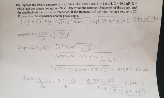
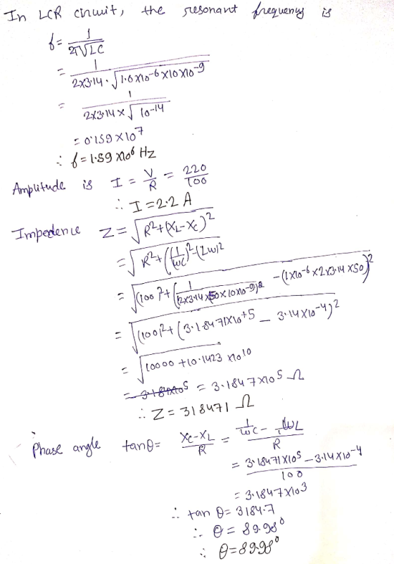
(b) Suppose the circuit parameters in a series...
Please help me solve this! All parts please 4. (a) Two slits with a separation of...
 Please help me solve this! All parts please
4. (a) Two slits with a separation of 8.0 x 10⁻⁵ m create an interference pattern on a screen 4.0 m away. If the tenth bright fringe above the central fringe is a linear distance of 12 cm from it, what is the wavelength of light used in the experiment? (b) Suppose the circuit parameters in a series RLC circuit are: L = 1.0 uH, C = 10.0 nF, R = 10092,...
Please help me solve this! All parts please
4. (a) Two slits with a separation of 8.0 x 10⁻⁵ m create an interference pattern on a screen 4.0 m away. If the tenth bright fringe above the central fringe is a linear distance of 12 cm from it, what is the wavelength of light used in the experiment? (b) Suppose the circuit parameters in a series RLC circuit are: L = 1.0 uH, C = 10.0 nF, R = 10092,...
a series resonant circuit has an AC source voltage of 10 V at a phase angle...
a series resonant circuit has an AC source voltage of 10 V at a phase angle of 0 degrees. The following are values for R, XL, XC respectively are: 2 Ohms, 10 Ohms, and 10 Ohms. Find I, VR, VL, VC, Q, BW, power dissipated at the half-power points. (Fr=5kHz)
Consider an RLC series circuit with R = 600 Ω, L = 3 H, C =...
Consider an RLC series circuit with R = 600 Ω, L = 3 H, C = 4μF, generator voltage V = 20 v, frequency= 60 hz. Find a) the inductive impedance XL, b) capacitive impedance Xc , c) Total impedance Z, d) Line current I , e) Voltage drops VR , VL, ,Vc f) combination voltage VRL , and VLc , g) phase angle φ , h) resonant frequency f0 , i) Power dissipated by circuit.
A phasor diagram is drawn for a series RLC circuit driven by a source of alternating...
 A phasor diagram is drawn for a series RLC circuit driven by a source of alternating (sinusoidal) voltage. Four phasors are drawn: VL, I, Vc, and VR at a particular instant in time. The frequency of the voltage source (i.e. the signal generator) is set to a value larger than the resonant frequency of the circuit. a. Label each phasor appropriately and identify the angle indicated by the arc with its appropriate label. b. Draw a fifth phasor on the...
A series RLC circuit has a 242 Hz resonant frequency, and is driven by an AC...
 A series RLC circuit has a 242 Hz resonant frequency, and is
driven by an AC voltage source at 315 Hz. The circuit has a 75.0
resistor and a
66.0 mH inductor. The maximum current is 1.20 A.
a) Find the capacitance in the circuit.
b) Find the maximum voltage of the source.
c) Find the average power of the circuit
d) Find the phase angle .
A series RLC circuit has a 242 Hz resonant frequency, and is
driven by an AC voltage source at 315 Hz. The circuit has a 75.0
resistor and a
66.0 mH inductor. The maximum current is 1.20 A.
a) Find the capacitance in the circuit.
b) Find the maximum voltage of the source.
c) Find the average power of the circuit
d) Find the phase angle .
Part A: What is the impedance of the circuit? Part B: What is the current amplitude?...
 Part A: What is the impedance of the circuit?
Part B: What is the current amplitude?
Part C: What is the phase angle of the source voltage with
respect to the current?
Part D: Does the source voltage lag or lead the current?
Part E: What is the voltage amplitude across the resistor?
Part F: What is the voltage amplitude across the inductor?
Part G: What is the voltage amplitudes across the capacitor?
Constants You have a resistor of resistance...
Part A: What is the impedance of the circuit?
Part B: What is the current amplitude?
Part C: What is the phase angle of the source voltage with
respect to the current?
Part D: Does the source voltage lag or lead the current?
Part E: What is the voltage amplitude across the resistor?
Part F: What is the voltage amplitude across the inductor?
Part G: What is the voltage amplitudes across the capacitor?
Constants You have a resistor of resistance...
1) An RLC series circuit has a 40.0 ? resistor, a 3.00 mH inductor, and a...
 1) An RLC series circuit has a 40.0 ? resistor, a 3.00 mH inductor, and a 5.00 ?F capacitor a. Find the circuit's impedance at 60.0 Hz and 10.0 kHz b. If the voltage source has Vrms 120 V, what is Irms at each frequency? c. Find the resonant frequency d. Calculate Irms at resonant frequency, if the voltage source is Vrms-120v e. Calculate the power factor and phase angle at 60.0 Hz
An RLC series circuit is constructed with R = 190.0 Ω, C = 6.00 µF, and...
An RLC series circuit is constructed with R = 190.0 Ω, C = 6.00 µF, and L = 0.54 H. The circuit is connected to an AC generator with a frequency of 60.0 Hz that delivers a maximum current of 2.30 A to the circuit. (a) What is the impedance of this circuit? ___ Ω (b) What are the maximum potential differences across each of the three circuit elements (R, L, and C)? VR, max =___ V VL, max =___...
A series LRC circuit is driven by an ac source with a voltage amplitude of 36.0...
 A series LRC circuit is driven by an ac source with a voltage amplitude of 36.0 V and a frequency of 60.0 Hz. The resistance is 160 Ohm, the inductance is 0.230 H, and the capacitance is 70.0 mu F. a) Determine the impedance of the circuit. b) Determine the current amplitude. c) Determine the voltage amplitude across (i) the resistor, (ii) the inductor and (iii) the capacitor. d) Sketch the phasor diagram (at t = 0) for the circuit,...
A series RLC circuit that has an inductance of 6 mH, a capacitance of 3 μF,...
 A series RLC circuit that has an inductance of 6 mH, a capacitance of 3 μF, and a resistance of 7.2 is driven by an ideal ac voltage source that has a peak emf of 110 V (a) Find the resonant frequency 1.19 rad/s (b) Find the root-means-square current at resonance When the frequency is 8000 rad/s, find the following values. (c) the capacitive and inductive reactances (d) the impedance (e) the root-mean square current. (f) the phase angle δ...
 Please help me solve this! All parts please
4. (a) Two slits with a separation of 8.0 x 10⁻⁵ m create an interference pattern on a screen 4.0 m away. If the tenth bright fringe above the central fringe is a linear distance of 12 cm from it, what is the wavelength of light used in the experiment? (b) Suppose the circuit parameters in a series RLC circuit are: L = 1.0 uH, C = 10.0 nF, R = 10092,...
Please help me solve this! All parts please
4. (a) Two slits with a separation of 8.0 x 10⁻⁵ m create an interference pattern on a screen 4.0 m away. If the tenth bright fringe above the central fringe is a linear distance of 12 cm from it, what is the wavelength of light used in the experiment? (b) Suppose the circuit parameters in a series RLC circuit are: L = 1.0 uH, C = 10.0 nF, R = 10092,...
 A phasor diagram is drawn for a series RLC circuit driven by a source of alternating (sinusoidal) voltage. Four phasors are drawn: VL, I, Vc, and VR at a particular instant in time. The frequency of the voltage source (i.e. the signal generator) is set to a value larger than the resonant frequency of the circuit. a. Label each phasor appropriately and identify the angle indicated by the arc with its appropriate label. b. Draw a fifth phasor on the...
 A series RLC circuit has a 242 Hz resonant frequency, and is
driven by an AC voltage source at 315 Hz. The circuit has a 75.0
resistor and a
66.0 mH inductor. The maximum current is 1.20 A.
a) Find the capacitance in the circuit.
b) Find the maximum voltage of the source.
c) Find the average power of the circuit
d) Find the phase angle .
A series RLC circuit has a 242 Hz resonant frequency, and is
driven by an AC voltage source at 315 Hz. The circuit has a 75.0
resistor and a
66.0 mH inductor. The maximum current is 1.20 A.
a) Find the capacitance in the circuit.
b) Find the maximum voltage of the source.
c) Find the average power of the circuit
d) Find the phase angle .
 Part A: What is the impedance of the circuit?
Part B: What is the current amplitude?
Part C: What is the phase angle of the source voltage with
respect to the current?
Part D: Does the source voltage lag or lead the current?
Part E: What is the voltage amplitude across the resistor?
Part F: What is the voltage amplitude across the inductor?
Part G: What is the voltage amplitudes across the capacitor?
Constants You have a resistor of resistance...
Part A: What is the impedance of the circuit?
Part B: What is the current amplitude?
Part C: What is the phase angle of the source voltage with
respect to the current?
Part D: Does the source voltage lag or lead the current?
Part E: What is the voltage amplitude across the resistor?
Part F: What is the voltage amplitude across the inductor?
Part G: What is the voltage amplitudes across the capacitor?
Constants You have a resistor of resistance...
 1) An RLC series circuit has a 40.0 ? resistor, a 3.00 mH inductor, and a 5.00 ?F capacitor a. Find the circuit's impedance at 60.0 Hz and 10.0 kHz b. If the voltage source has Vrms 120 V, what is Irms at each frequency? c. Find the resonant frequency d. Calculate Irms at resonant frequency, if the voltage source is Vrms-120v e. Calculate the power factor and phase angle at 60.0 Hz
 A series LRC circuit is driven by an ac source with a voltage amplitude of 36.0 V and a frequency of 60.0 Hz. The resistance is 160 Ohm, the inductance is 0.230 H, and the capacitance is 70.0 mu F. a) Determine the impedance of the circuit. b) Determine the current amplitude. c) Determine the voltage amplitude across (i) the resistor, (ii) the inductor and (iii) the capacitor. d) Sketch the phasor diagram (at t = 0) for the circuit,...
 A series RLC circuit that has an inductance of 6 mH, a capacitance of 3 μF, and a resistance of 7.2 is driven by an ideal ac voltage source that has a peak emf of 110 V (a) Find the resonant frequency 1.19 rad/s (b) Find the root-means-square current at resonance When the frequency is 8000 rad/s, find the following values. (c) the capacitive and inductive reactances (d) the impedance (e) the root-mean square current. (f) the phase angle δ...
Most questions answered within 3 hours.
-
which of the following may lead to speciation?
a. a group of individuals from a mainland...
asked 4 minutes ago -
Please I need today answer for This question and it is very
important and I need...
asked 22 minutes ago -
Five years from today, you plan to invest $3,700 for 7
additional years at 5.8 percent...
asked 22 minutes ago -
GDL just paid a dividend of $4.06 per share. You expect
dividends to grow 12% for...
asked 24 minutes ago -
which of the following is a basic compound?
vinegar
orange juice
seltzer
none of the above
asked 27 minutes ago -
5. Suppose you obtained 0.55 g of crude clove oil from 7.0 g of
fresh cloves....
asked 37 minutes ago -
Provide a paragraph of introduction that generally describes
cognitive development over the lifespan.
asked 42 minutes ago -
In a market, when the price increased the total expenditure on
the good also increased. Is...
asked 42 minutes ago -
If 5.70 g of potassium react with water, how many grams of
hydrogen gas, H2, are...
asked 56 minutes ago -
How many moles of CO2 and H2O will be
produced by combustion analysis of 0.010 mol...
asked 54 minutes ago -
Tennis champion Maria Sharapova is capable of serving a tennis
ball at 126 mph.
b) What...
asked 1 hour ago -
The electric potential V in the space between the plates of a
given vacuum tube is...
asked 1 hour ago