
7) The force of the deltoid is greater than / less than (circle one) the weight of the arm. Use the idea of "lever arm" to explain why this answer makes sense. 8) Now consider the force on the arm by the shoulder joint. For Fnet, x and Fnet, y to both be zero, the shoulder joint must pull to the left / push to the right (circle one) on the arm, and the shoulder joint must push down / up (circle one) on the arm. 9) Does your extended free body diagram need a revision? If so, do that now. 10) Fill in the static equilibrium conditions for forces, Faet, x 0 and Fnet, y 0, with the details of this problem and then solve for N, and Ny. Your answers should be expressions in terms of the "knowns" 11) Plug in the values given on the previous page for the "knowns" to find values for N, and Ny. 12) As a final test to see if you've made any mistakes, treat the center of mass of the arm as the axis of rotation and compute Tnet E t. If you haven't made any mistakes, this sum should be zero (because it's a static equilibrium situation!)
Homework Answers
 If you have any doubts comment
below, please rate thumbsup.
If you have any doubts comment
below, please rate thumbsup.
Add Answer to:
4) Read the following and revise your free body diagram as necessary A common confusion when...
nutaud 4) Read the following and revise your free body diagram as necessary. A common confusion...
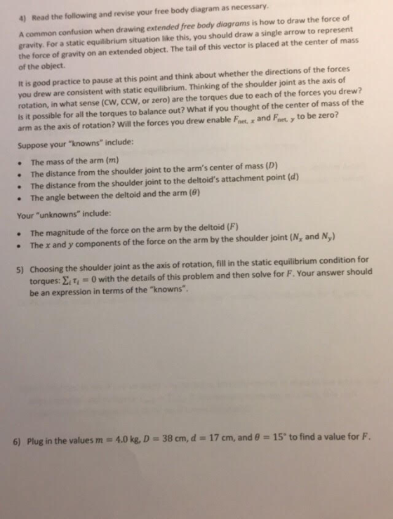
 nutaud 4) Read the following and revise your free body diagram as necessary. A common confusion when drawing extended free body diagrams is how to draw the force of gravity. For a static equilibrium situation like this, you should draw a single arrow to represent the force of gravity on an extended object. The tail of this vector is placed at the center of mass of the object. It is good practice to pause at this point and think about...
please answer in full detail 4. Use the drawing below as a model of forces involved...
 please answer in full detail
4. Use the drawing below as a model of forces involved in holding an outstretched arm stationary, let Fu model the "deltoid muscle, which provides tension at an angle of to the bones and _cm represent the center of mass of the arm. X_M12 cm x cm 24 cm mass of the arm - 3.3 kg 015 a. the shoulder joint labeled in the above figure but decomposed into it's - and y. components in...
please answer in full detail
4. Use the drawing below as a model of forces involved in holding an outstretched arm stationary, let Fu model the "deltoid muscle, which provides tension at an angle of to the bones and _cm represent the center of mass of the arm. X_M12 cm x cm 24 cm mass of the arm - 3.3 kg 015 a. the shoulder joint labeled in the above figure but decomposed into it's - and y. components in...
Can you help finish drawing the free body diagram for question #5? Also I need help...
 Can you help finish drawing the free body diagram for question
#5?
Also I need help with #6 for calculating torque and filling in
the table.
I will rate thank you!
Name: Balance Lab (Part 1) Date: Explore the "Balance Lab" section of the Balancing Act simulation. 4. Create a situation in which the beam is balanced (without the supports) while there is a single collection of bricks on one side of the pivot and two different collections of bricks...
Can you help finish drawing the free body diagram for question
#5?
Also I need help with #6 for calculating torque and filling in
the table.
I will rate thank you!
Name: Balance Lab (Part 1) Date: Explore the "Balance Lab" section of the Balancing Act simulation. 4. Create a situation in which the beam is balanced (without the supports) while there is a single collection of bricks on one side of the pivot and two different collections of bricks...
Rotational Dynamics Assignment (200 Points) • Due Friday, July 31 at 5:00 pm Equations are in...
 Rotational Dynamics Assignment (200 Points) • Due Friday, July 31 at 5:00 pm Equations are in a separate document entitled “Equations for Rotational Dynamics Assignment” • Moments of inertia formulas are provided on the last page of this document • Show all of your work when solving equations. It is not sufficient to merely have a correct numerical answer. You need to have used legitimate equations and algebra. You also need to have correctly used the data. • Units must...
Problem 3. (20 points) Consider the following simplified model of a person in static equilibrium in...
 Problem 3. (20 points) Consider the following simplified model of a person in static equilibrium in a yoga pose. The diagram below shows the upward normal forces acting on the hands and feet, as well as the downward weight forces on the upper and lower body. There are also horizontal static friction forces on the hands and feet not shown in this diagram. Assume the weight of the lower body has magnitude 250 N and the weight of the upper...
Procedure 1, 2, 3 Mass of a clamp: 21.5 True mass of meter stick: _133.6 g...
 Procedure 1, 2, 3 Mass of a clamp: 21.5 True mass of meter stick: _133.6 g Center of mass of meter stick: _50 cm True weight of unknown mass: _212.99_ Procedure 4 Position of the 100-g mass: 10.0 cm Position of equilibrium: _30.9 cm Mass of the stick from method of torques: Procedure 5 Position of the 100-g mass: 10.0 cm Position of the 200-g mass: _90.0 cm Position of equilibrium of meter stick: Procedure 6 Position of unknown mass...
Try to show all of the following steps for the problem below: Draw a free-body diagram...
Try to show all of the following steps for the problem below: Draw a free-body diagram for at least one object (or system) with vectors showing all forces on that object. Draw a coordinate system for each free-body diagram and label the axes clearly. Write Newton’s Second Law in component form for each object (that is: write ∑Fx = max , ∑Fy = may , etc) Write down any constraints for the system based on what you know about its...
A student is riding their bike when they come across a turn in the form of a circular arc of radius R 3.0m as pictured in the diagram below and travel along this arc in the clockwise direction. At on...
 A student is riding their bike when they come across a turn in the form of a circular arc of radius R 3.0m as pictured in the diagram below and travel along this arc in the clockwise direction. At one point along this trajectory (the origin of the given coordinate system) it makes sense to define the Cartesian coordinate system shown where the x-axis is tangent to the trajectory and the y-axis is perpendicular to it. At this point the...
Question 5. Consider the following four obiects: a hoop, a flat disk,a solid sphere, and a...
 Question 5. Consider the following four obiects: a hoop, a flat disk,a solid sphere, and a hollow sphere. Each of the objects has mass M and radius R. The axis of rotation passes through the center of each object, and is perpendicular to the plane of the hoop and the plane of the flat disk. Which of these objects requires the largest torque to give it the same angular acceleration? A) the hoop D) the flat disk B) the hollow...
 nutaud 4) Read the following and revise your free body diagram as necessary. A common confusion when drawing extended free body diagrams is how to draw the force of gravity. For a static equilibrium situation like this, you should draw a single arrow to represent the force of gravity on an extended object. The tail of this vector is placed at the center of mass of the object. It is good practice to pause at this point and think about...
 please answer in full detail
4. Use the drawing below as a model of forces involved in holding an outstretched arm stationary, let Fu model the "deltoid muscle, which provides tension at an angle of to the bones and _cm represent the center of mass of the arm. X_M12 cm x cm 24 cm mass of the arm - 3.3 kg 015 a. the shoulder joint labeled in the above figure but decomposed into it's - and y. components in...
please answer in full detail
4. Use the drawing below as a model of forces involved in holding an outstretched arm stationary, let Fu model the "deltoid muscle, which provides tension at an angle of to the bones and _cm represent the center of mass of the arm. X_M12 cm x cm 24 cm mass of the arm - 3.3 kg 015 a. the shoulder joint labeled in the above figure but decomposed into it's - and y. components in...
 Can you help finish drawing the free body diagram for question
#5?
Also I need help with #6 for calculating torque and filling in
the table.
I will rate thank you!
Name: Balance Lab (Part 1) Date: Explore the "Balance Lab" section of the Balancing Act simulation. 4. Create a situation in which the beam is balanced (without the supports) while there is a single collection of bricks on one side of the pivot and two different collections of bricks...
Can you help finish drawing the free body diagram for question
#5?
Also I need help with #6 for calculating torque and filling in
the table.
I will rate thank you!
Name: Balance Lab (Part 1) Date: Explore the "Balance Lab" section of the Balancing Act simulation. 4. Create a situation in which the beam is balanced (without the supports) while there is a single collection of bricks on one side of the pivot and two different collections of bricks...
 Rotational Dynamics Assignment (200 Points) • Due Friday, July 31 at 5:00 pm Equations are in a separate document entitled “Equations for Rotational Dynamics Assignment” • Moments of inertia formulas are provided on the last page of this document • Show all of your work when solving equations. It is not sufficient to merely have a correct numerical answer. You need to have used legitimate equations and algebra. You also need to have correctly used the data. • Units must...
 Problem 3. (20 points) Consider the following simplified model of a person in static equilibrium in a yoga pose. The diagram below shows the upward normal forces acting on the hands and feet, as well as the downward weight forces on the upper and lower body. There are also horizontal static friction forces on the hands and feet not shown in this diagram. Assume the weight of the lower body has magnitude 250 N and the weight of the upper...
 Procedure 1, 2, 3 Mass of a clamp: 21.5 True mass of meter stick: _133.6 g Center of mass of meter stick: _50 cm True weight of unknown mass: _212.99_ Procedure 4 Position of the 100-g mass: 10.0 cm Position of equilibrium: _30.9 cm Mass of the stick from method of torques: Procedure 5 Position of the 100-g mass: 10.0 cm Position of the 200-g mass: _90.0 cm Position of equilibrium of meter stick: Procedure 6 Position of unknown mass...
 A student is riding their bike when they come across a turn in the form of a circular arc of radius R 3.0m as pictured in the diagram below and travel along this arc in the clockwise direction. At one point along this trajectory (the origin of the given coordinate system) it makes sense to define the Cartesian coordinate system shown where the x-axis is tangent to the trajectory and the y-axis is perpendicular to it. At this point the...
 Question 5. Consider the following four obiects: a hoop, a flat disk,a solid sphere, and a hollow sphere. Each of the objects has mass M and radius R. The axis of rotation passes through the center of each object, and is perpendicular to the plane of the hoop and the plane of the flat disk. Which of these objects requires the largest torque to give it the same angular acceleration? A) the hoop D) the flat disk B) the hollow...
Most questions answered within 3 hours.
-
questions for Biology lab
An agarose gel electrophoresis assay performed with high quality
will NOT have...
asked 40 seconds from now -
A spring with spring constant 400 N/m is anchored at the bottom
of a frictionless 30^∘...
asked 2 minutes ago -
The half-life of 238U is 4.5×10⁹ yr.
Find the number of disintegrations per hour emitted by...
asked 11 minutes ago -
y[n] = x[n] - 3x[n - 1] + 4x[n - 2]
What is the transfer function...
asked 17 minutes ago -
Which one of the following statements is TRUE?
a.
An agency relationship is when someone hires...
asked 31 minutes ago -
Consider the liquid phase reaction : A ---> Products which is
to take place in a...
asked 39 minutes ago -
QUESTION ONE: For the following reaction, 13.4 grams of chlorine
gas are allowed to react with...
asked 45 minutes ago -
An
Atwood's machine has one block of m1 = 0.370 kg and the other is of...
asked 47 minutes ago -
Why is Kevlar a stronger fabric then dacron? Provide two reasons
involving structures.
asked 1 hour ago -
Suppose you have a checkers board. (8 squares wide and 8
squares long) and you
have...
asked 1 hour ago -
Given the following function: QD = 200 - 5.25P
7.1 Derive the Regular Demand Function
7.2...
asked 1 hour ago -
The following results were obtained as
part of a multiple regression analysis involving 3 independent
variables:...
asked 2 hours ago