 Could you please use 15th
edition of AISC Manual for proper solution.
Could you please use 15th
edition of AISC Manual for proper solution.
400 182 ft-k 12' 140 ft- 400
Homework Answers


Add Answer to:
Could you please use 15th
edition of AISC Manual for proper solution.
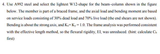
4. Use A992 steel...
(Text 6.8-6) The member shown in Figure P6.8-6 is part of a braced frame.
 (Text 6.8-6) The member shown in Figure P6.8-6 is part of a braced frame. The axial load and end moments are based on service loads composed of equal parts dead load and live load. The frame analysis was performed consistent with the effective length method, so the flexural rigidity, El, was unreduced. Select a W shape of A992 steel.
Could you please use AISC steel manual for the parts needed? 15th edition. 4. The beam...
 Could you please use AISC steel
manual for the parts needed? 15th edition.
4. The beam shown the Figure has lateral support only at the ends. The uniform load is a superimposed dead load, and the concentrated load is a live load. Use A992 steel and select an economical W shape. The live load deflection must not exceed L/360 (you may use the tables of Chapter 3). Also, calculate Fer for the selected W shape 25 k/ft A 15 15"...
Could you please use AISC steel
manual for the parts needed? 15th edition.
4. The beam shown the Figure has lateral support only at the ends. The uniform load is a superimposed dead load, and the concentrated load is a live load. Use A992 steel and select an economical W shape. The live load deflection must not exceed L/360 (you may use the tables of Chapter 3). Also, calculate Fer for the selected W shape 25 k/ft A 15 15"...
Could you please use AISC steel manual for the parts needed? 15th edition 2. The frame...
 Could you please use AISC steel
manual for the parts needed? 15th edition
2. The frame shown in the figure below is unbraced, and bending is about the x-axis of all members. All beams are W16 x 40. Column BC is supported in the weak direction (i.e 2 direction perpendicular to the plane of the frame) at mid height and it is assumed pinned at both ends in this direction (i.e. Ky=1) Assuming that all columns are rectangular HSS 14x6x5/8,...
Could you please use AISC steel
manual for the parts needed? 15th edition
2. The frame shown in the figure below is unbraced, and bending is about the x-axis of all members. All beams are W16 x 40. Column BC is supported in the weak direction (i.e 2 direction perpendicular to the plane of the frame) at mid height and it is assumed pinned at both ends in this direction (i.e. Ky=1) Assuming that all columns are rectangular HSS 14x6x5/8,...
A W14 × 74 of A992 steel, 16 feet long, is used as a column in an unbraced frame.
 A W14 × 74 of A992 steel, 16 feet long, is used as a column in an unbraced frame. The axial load and end moments obtained from a first-order analysis of the gravity loads (dead load and live load) are shown in Figure P6.7-2a. The frame is symmetric, and the gravity loads are symmetrically placed. Figure P6.7-2b shows the wind load effects obtained from a first-order analysis. All loads and moments are based on service loads, and all bend-ing moments...
Please show all steps and cite all AISC formulas. Thanks 5) Compression combined with bending -...
 Please show all steps and cite all AISC formulas. Thanks
5) Compression combined with bending - design AW-section beam-column member is to be used in a braced frame, and must support factored LRFD loads of Pu 600k and moments Mux = 330 k*ft (these loads were derived through use of a rigorous 2nd-order analysis and include notional loads). The member is 18ft long and totally unbraced with respect to both flexural buckling (for compression) and lateral-torsional buckling (for flexure). Choose...
Please show all steps and cite all AISC formulas. Thanks
5) Compression combined with bending - design AW-section beam-column member is to be used in a braced frame, and must support factored LRFD loads of Pu 600k and moments Mux = 330 k*ft (these loads were derived through use of a rigorous 2nd-order analysis and include notional loads). The member is 18ft long and totally unbraced with respect to both flexural buckling (for compression) and lateral-torsional buckling (for flexure). Choose...
2. Design Wide flange column section only of A992 steel to serve as a pinned- end main member column 30 ft long to carry an axial compression loads in a braced structure, based on AISC LRFD metho...
 2. Design Wide flange column section only of A992 steel to serve as a pinned- end main member column 30 ft long to carry an axial compression loads in a braced structure, based on AISC LRFD method. The dead load is 50 kips A992 13-0" and live load is 70 kips. The member has strong axis direction supported at 17ft height from the bottom of the column. Dead load is 20 kips and live load is 40 kips. Assume the...
Please write very clearly. Determine whether a W12x35 can work if A992 steel is used considering...
 Please write very clearly.
Determine whether a W12x35 can work if A992 steel is used
considering the conditions stated above.
5.5-4 The beam shown in Figure P5.5-4 has continuous lateral support of both flanges. The uniform load is a service load consisting of 50% dead load and 50% live load. The dead load includes the weight of the beam. If A992 steel is used, is a W12 x 35 adequate? a. Use LRFD. 6.5 k/ft |6- — 18– 767
Please write very clearly.
Determine whether a W12x35 can work if A992 steel is used
considering the conditions stated above.
5.5-4 The beam shown in Figure P5.5-4 has continuous lateral support of both flanges. The uniform load is a service load consisting of 50% dead load and 50% live load. The dead load includes the weight of the beam. If A992 steel is used, is a W12 x 35 adequate? a. Use LRFD. 6.5 k/ft |6- — 18– 767
The single-story unbraced frame shown below is subjected to dead load, roof live load, and wind load Figure 1 shows the...
 The single-story unbraced frame shown below is subjected to dead load, roof live load, and wind load Figure 1 shows the results of a first-order analysis relative to the columns of the frame. The axial load and end moment (also equal to the maximum moment in the column) are given separately for the different load cases (i.e., dead load, roof live load, and lateral wind load). All vertical loads are symmetrically placed and contribute only to the Mnt moments (i.e.,...
Problem 22. Two-story, one-bay unbraced frame shown below is subjected to gravitational dead and live loads...
 Problem 22. Two-story, one-bay unbraced frame shown below is subjected to gravitational dead and live loads and wind lateral load. The columns are made of W18x65 (I,-1070 in , Ag- 19.1 in2, r-7.49 in, ry-1.69 in) and beams are made of W18x71 (1, 1170 in). The table below shows the moments at the ends of column 4-5 due to three load cases. The frame is fully braced in lateral direction. Use Grade50 steel Bending is about strong axis. All gravity...
Don’t do the extra credit. Just the regular problem. The single-story unbraced frame shown below is...
 Don’t do the extra credit. Just the regular problem.
The single-story unbraced frame shown below is subjected to dead load, roof live load, and wind load Figure I shows the results of a first-order analysis selative to the columns of the frame The axial load and end moment (also equal to the maximum moment in the column) are given separately for the diffierent load cases (i e, dead load, roof live load, and lateral wind load) All vertical loads are...
Don’t do the extra credit. Just the regular problem.
The single-story unbraced frame shown below is subjected to dead load, roof live load, and wind load Figure I shows the results of a first-order analysis selative to the columns of the frame The axial load and end moment (also equal to the maximum moment in the column) are given separately for the diffierent load cases (i e, dead load, roof live load, and lateral wind load) All vertical loads are...
 Could you please use AISC steel
manual for the parts needed? 15th edition.
4. The beam shown the Figure has lateral support only at the ends. The uniform load is a superimposed dead load, and the concentrated load is a live load. Use A992 steel and select an economical W shape. The live load deflection must not exceed L/360 (you may use the tables of Chapter 3). Also, calculate Fer for the selected W shape 25 k/ft A 15 15"...
Could you please use AISC steel
manual for the parts needed? 15th edition.
4. The beam shown the Figure has lateral support only at the ends. The uniform load is a superimposed dead load, and the concentrated load is a live load. Use A992 steel and select an economical W shape. The live load deflection must not exceed L/360 (you may use the tables of Chapter 3). Also, calculate Fer for the selected W shape 25 k/ft A 15 15"...
 Could you please use AISC steel
manual for the parts needed? 15th edition
2. The frame shown in the figure below is unbraced, and bending is about the x-axis of all members. All beams are W16 x 40. Column BC is supported in the weak direction (i.e 2 direction perpendicular to the plane of the frame) at mid height and it is assumed pinned at both ends in this direction (i.e. Ky=1) Assuming that all columns are rectangular HSS 14x6x5/8,...
Could you please use AISC steel
manual for the parts needed? 15th edition
2. The frame shown in the figure below is unbraced, and bending is about the x-axis of all members. All beams are W16 x 40. Column BC is supported in the weak direction (i.e 2 direction perpendicular to the plane of the frame) at mid height and it is assumed pinned at both ends in this direction (i.e. Ky=1) Assuming that all columns are rectangular HSS 14x6x5/8,...
 Please show all steps and cite all AISC formulas. Thanks
5) Compression combined with bending - design AW-section beam-column member is to be used in a braced frame, and must support factored LRFD loads of Pu 600k and moments Mux = 330 k*ft (these loads were derived through use of a rigorous 2nd-order analysis and include notional loads). The member is 18ft long and totally unbraced with respect to both flexural buckling (for compression) and lateral-torsional buckling (for flexure). Choose...
Please show all steps and cite all AISC formulas. Thanks
5) Compression combined with bending - design AW-section beam-column member is to be used in a braced frame, and must support factored LRFD loads of Pu 600k and moments Mux = 330 k*ft (these loads were derived through use of a rigorous 2nd-order analysis and include notional loads). The member is 18ft long and totally unbraced with respect to both flexural buckling (for compression) and lateral-torsional buckling (for flexure). Choose...
 2. Design Wide flange column section only of A992 steel to serve as a pinned- end main member column 30 ft long to carry an axial compression loads in a braced structure, based on AISC LRFD method. The dead load is 50 kips A992 13-0" and live load is 70 kips. The member has strong axis direction supported at 17ft height from the bottom of the column. Dead load is 20 kips and live load is 40 kips. Assume the...
 Please write very clearly.
Determine whether a W12x35 can work if A992 steel is used
considering the conditions stated above.
5.5-4 The beam shown in Figure P5.5-4 has continuous lateral support of both flanges. The uniform load is a service load consisting of 50% dead load and 50% live load. The dead load includes the weight of the beam. If A992 steel is used, is a W12 x 35 adequate? a. Use LRFD. 6.5 k/ft |6- — 18– 767
Please write very clearly.
Determine whether a W12x35 can work if A992 steel is used
considering the conditions stated above.
5.5-4 The beam shown in Figure P5.5-4 has continuous lateral support of both flanges. The uniform load is a service load consisting of 50% dead load and 50% live load. The dead load includes the weight of the beam. If A992 steel is used, is a W12 x 35 adequate? a. Use LRFD. 6.5 k/ft |6- — 18– 767
 The single-story unbraced frame shown below is subjected to dead load, roof live load, and wind load Figure 1 shows the results of a first-order analysis relative to the columns of the frame. The axial load and end moment (also equal to the maximum moment in the column) are given separately for the different load cases (i.e., dead load, roof live load, and lateral wind load). All vertical loads are symmetrically placed and contribute only to the Mnt moments (i.e.,...
 Problem 22. Two-story, one-bay unbraced frame shown below is subjected to gravitational dead and live loads and wind lateral load. The columns are made of W18x65 (I,-1070 in , Ag- 19.1 in2, r-7.49 in, ry-1.69 in) and beams are made of W18x71 (1, 1170 in). The table below shows the moments at the ends of column 4-5 due to three load cases. The frame is fully braced in lateral direction. Use Grade50 steel Bending is about strong axis. All gravity...
 Don’t do the extra credit. Just the regular problem.
The single-story unbraced frame shown below is subjected to dead load, roof live load, and wind load Figure I shows the results of a first-order analysis selative to the columns of the frame The axial load and end moment (also equal to the maximum moment in the column) are given separately for the diffierent load cases (i e, dead load, roof live load, and lateral wind load) All vertical loads are...
Don’t do the extra credit. Just the regular problem.
The single-story unbraced frame shown below is subjected to dead load, roof live load, and wind load Figure I shows the results of a first-order analysis selative to the columns of the frame The axial load and end moment (also equal to the maximum moment in the column) are given separately for the diffierent load cases (i e, dead load, roof live load, and lateral wind load) All vertical loads are...
Most questions answered within 3 hours.
-
Humans have used horses for transportation for millions of
years. Therefore, they will use horses for...
asked 1 hour ago -
The following are the Jensen Corporation's unit costs of making
and selling an item at a...
asked 2 hours ago -
Does direct Medicare reimbursement of Advanced practice nurses
increase access to their services?
asked 3 hours ago -
List and explain why a company would choose to use a
published
compensation survey vs. creating...
asked 3 hours ago -
A discrete random variable X can take values from 1 to 10. Find
the variance of...
asked 3 hours ago -
The primary financial goal of a corporation is to maximize:
shareholders wealth.
earnings per share.
stock...
asked 3 hours ago -
determine whether the vectors u=(1,2,3,), v=(-2,1,0) and
w=(1,0,1) are linearly dependent or independent.
asked 3 hours ago -
python
Define a function called print_values which takes a dictionary
object as a parameter. The function...
asked 4 hours ago -
In Chapter 1 you created a program named Triangle in
which you displayed a seven-line triangle...
asked 4 hours ago -
Research question: What are the differences between separately
stated and non separately stated transactions in an...
asked 5 hours ago -
By using Arduino write a code that connects two LEDs to two
push-buttons. Each button controls...
asked 6 hours ago -
Bank of America has bonds that pay a coupon interest rate of 5.5
percent and mature...
asked 6 hours ago