
Homework Answers

Add Answer to:
2. As shown in Fig. 2, the input source is a pure sinusoidal wave. The peak...
breakdown, with respect to the input voltag. 4. BONUS: Fig. 5 presents a half sinusoidal, with...
 breakdown, with respect to the input voltag. 4. BONUS: Fig. 5 presents a half sinusoidal, with 2V peak-to-peak, no DC offset. Fig. 5 presents a half wave rectifier. We assume Vin here is aw the Vout waveform when the diode has 0.7V voltage drop. Diode + 7 + vin Load Svout AC Voltage vir Source Fig.5. Half wave rectifier circuit
A sinusoidal ac voltage source with a peak voltage of 28.3 V is connected across a...
A sinusoidal ac voltage source with a peak voltage of 28.3 V is connected across a pure resistive load. Choose the best answer for the dc voltage resulting in the same average power dissipated in the load? A) 28.3V B) 56.6 V C) 20 V D) 10 V
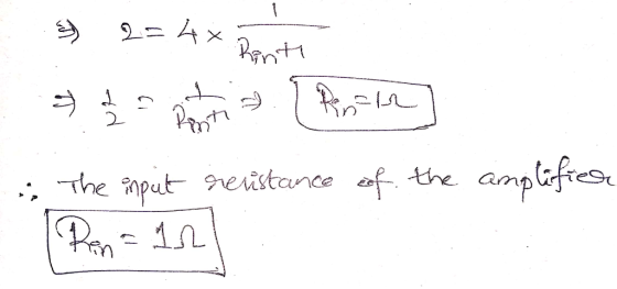
A 1V peak input sine wave is amplified to 9V peak across a 1kW load. The...
A 1V peak input sine wave is amplified to 9V peak across a 1kW load. The input current of the amplifier is a sine wave of 0.1 mA peak. The amplifier draws 9.5 mA from each of its +/- 10 V DC power supplies. Find h, the efficiency of the amplifier.
An amplifier operating from ±5 V supplies provides a 3 V peak sine wave across a...
An amplifier operating from ±5 V supplies provides a 3 V peak sine wave across a 30 Ω load when provided with a 20 mV peak input from which 20 μA peak is drawn. The average current in each supply is measured to be 50 mA. Find the voltage gain, current gain, and power gain expressed as ratios, and the amplifier efficiency.
2. (a) Consider a non-ideal voltage source modeled as an ideal voltage source in series with...
 2. (a) Consider a non-ideal voltage source modeled as an ideal voltage source in series with an unknown resistance, R. Derive an expression for the resistance, R, in terms of the voltage, V, measured with no load and the voltage, V', measured across a load of resistance RL. (b) Consider a non-ideal voltage source modeled as an ideal current source in parallel with an unknown resistance, R. Derive an expression for the resistance, R, in terms of the voltage, V,...
Consider the single-phase full-wave rectifier circuit shown below with a sinusoidal input vs 120 Vrms at...
 Consider the single-phase full-wave rectifier circuit shown below with a sinusoidal input vs 120 Vrms at 60 Hz and a load R= 250 TiD DAZ 40 AD AD ww D (a) (b) Consider adding a filter capacitor to the full-wave rectifier in Problem 3 to reduce the output ripple (a) Calculate the minimum value of capacitance required to reduce the output voltage ripple to 1 % of the average value (b) Calculate the average output current (c) Calculate the average...
A chopper is feeding an RL load as shown in Fig. 2 with V= 220-V, R...
 A chopper is feeding an RL load as shown in Fig. 2 with V= 220-V, R = 10 Q, and L = 15.5 mH, f= 1-Khz, and E = 110-V and k = 0.4. Calculate: the instantaneous load currents. (a) (b) (c) (d) (e) the average load current Ia and the rms load current Io. the effective input resistance R;. the rms value of chopper current Ir. draw the voltage across the chopper SW and draw the current through Dm-...
The input to the circuit shown in Fig. 2 is the voltage source v(t). The output...
 The input to the circuit shown in Fig. 2 is the voltage source v(t). The output is the voltage across the capacitor, v(t). Determine the output of this circuit as a function of time t when the input is v.(t)-8+12u(t) V 40 18 s(t) 160 Fig. 2
Question 2 (10%) The input to the circuit shown in Fig. 2 is the voltage source...
 Question 2 (10%) The input to the circuit shown in Fig. 2 is the voltage source vs(t). The output is the voltage across two open terminals, vo(). If v()-3-(t) V, the output is the voltage vo()-10+Se30* V for 20. Determine the values of Ri and R2. 2 sa) olt) Fig. 2
(5pts) 11. A 0.5V peak-to-peak 1kHz sine wave with a 100mV DC offset is provided as...
 (5pts) 11. A 0.5V peak-to-peak 1kHz sine wave with a 100mV DC offset is provided as the input into a non- inverting operational amplifier with a gain of 20. If the output of the op-amp is read using an oscilloscope with AC coupling, then the value is close to a. 2V DC b. 2V peak-to-peak 1kHz sine wave c. 10V peak-to-peak 1kHz sine wave with 2V DC offset d. 10V peak-to-peak 1kHz sine wave only (5pts) 12. Which of the...
 breakdown, with respect to the input voltag. 4. BONUS: Fig. 5 presents a half sinusoidal, with 2V peak-to-peak, no DC offset. Fig. 5 presents a half wave rectifier. We assume Vin here is aw the Vout waveform when the diode has 0.7V voltage drop. Diode + 7 + vin Load Svout AC Voltage vir Source Fig.5. Half wave rectifier circuit
 2. (a) Consider a non-ideal voltage source modeled as an ideal voltage source in series with an unknown resistance, R. Derive an expression for the resistance, R, in terms of the voltage, V, measured with no load and the voltage, V', measured across a load of resistance RL. (b) Consider a non-ideal voltage source modeled as an ideal current source in parallel with an unknown resistance, R. Derive an expression for the resistance, R, in terms of the voltage, V,...
 Consider the single-phase full-wave rectifier circuit shown below with a sinusoidal input vs 120 Vrms at 60 Hz and a load R= 250 TiD DAZ 40 AD AD ww D (a) (b) Consider adding a filter capacitor to the full-wave rectifier in Problem 3 to reduce the output ripple (a) Calculate the minimum value of capacitance required to reduce the output voltage ripple to 1 % of the average value (b) Calculate the average output current (c) Calculate the average...
 A chopper is feeding an RL load as shown in Fig. 2 with V= 220-V, R = 10 Q, and L = 15.5 mH, f= 1-Khz, and E = 110-V and k = 0.4. Calculate: the instantaneous load currents. (a) (b) (c) (d) (e) the average load current Ia and the rms load current Io. the effective input resistance R;. the rms value of chopper current Ir. draw the voltage across the chopper SW and draw the current through Dm-...
 The input to the circuit shown in Fig. 2 is the voltage source v(t). The output is the voltage across the capacitor, v(t). Determine the output of this circuit as a function of time t when the input is v.(t)-8+12u(t) V 40 18 s(t) 160 Fig. 2
 Question 2 (10%) The input to the circuit shown in Fig. 2 is the voltage source vs(t). The output is the voltage across two open terminals, vo(). If v()-3-(t) V, the output is the voltage vo()-10+Se30* V for 20. Determine the values of Ri and R2. 2 sa) olt) Fig. 2
 (5pts) 11. A 0.5V peak-to-peak 1kHz sine wave with a 100mV DC offset is provided as the input into a non- inverting operational amplifier with a gain of 20. If the output of the op-amp is read using an oscilloscope with AC coupling, then the value is close to a. 2V DC b. 2V peak-to-peak 1kHz sine wave c. 10V peak-to-peak 1kHz sine wave with 2V DC offset d. 10V peak-to-peak 1kHz sine wave only (5pts) 12. Which of the...
Most questions answered within 3 hours.
-
You are the operations manager of a firm that uses the
continuous review inventory control system....
asked 2 hours ago -
Cost and fair value data for the trading debt securities of
Wildhorse Company at December 31,...
asked 4 hours ago -
In a population of jaguars, a gene with two alleles encodes the
fur color. Allele B...
asked 5 hours ago -
Two copper wires, one 1.80 times the diameter of the other, have
the same current flowing...
asked 5 hours ago -
9. In 2003 the price of ‘home heating oil’ substantially
increased during the harsh winter. In...
asked 5 hours ago -
Match the key paradoxes of negotiation.
Claiming Value
Sticking by your principles
Sticking with your strategy...
asked 6 hours ago -
Question text Suppose a sample of 28 observations is taken from
a population, and the sample...
asked 7 hours ago -
The mayor of a small town estimates that 33% of the
residents in the town favor...
asked 8 hours ago -
1. True or false: According to the Gordon Growth Model, firms
that pay dividends will always...
asked 8 hours ago -
20
Lansing Corporation reported net income of $67 million for last
year. Depreciation expense totaled $15...
asked 9 hours ago -
Write a MATLAB userdefined function that calculates the product and
the ratio of two variables x...
asked 9 hours ago -
Timia needs some cash in a hurry. She owns her car outright and
is considering a...
asked 9 hours ago