
Homework Answers

Add Answer to:
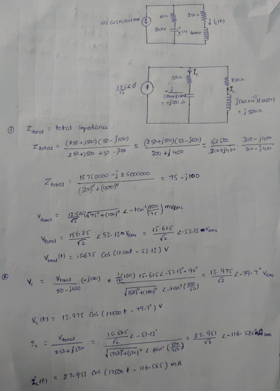
I. For the circuit in Fig. 5, use steady-state analysis to 5003 250 23 125cos(12,5001) mA...
20Ω 30 Ω j20Ω Fig. 1.7 In the circuit of Fig. 1.8, find the RMS phasor...
 20Ω 30 Ω j20Ω Fig. 1.7 In the circuit of Fig. 1.8, find the RMS phasor voltage V so that the 60 Ω resistor absorbs an average power of 240 W. Hence, determine the complex power delivered to each component, the complex power and the power factor delivered by voltage source. Fig. 1.8 2) P1.8
7. The expressions for the steady-state voltage and current at the terminals of the circuit seen...
 7. The expressions for the steady-state voltage and current at the terminals of the circuit seen in Fig. P9.14 are Ug = 300 cos (5000 + 78*) V, 's = 6 sin (5000?1+ 123°) A a) What is the impedance seen by the source? b) By how many microseconds is the current out of phase with the voltage? Figure P9.14 2, Circuit
250 22 Problem 3. (9 Points) In the adjoining circuit schematic, in steady-state, the current flowing...
 250 22 Problem 3. (9 Points) In the adjoining circuit schematic, in steady-state, the current flowing through the loop causes a voltage drop across the resistor, having the waveform vr(t) = 15 cos (75 t) and a voltage drop across the capacitor given by ve(t) = 20 cos (75 t +90) (a) Express the above two voltages in phasor form. (b) Find the source voltage shown in the circuit schematic, expressed in phasor form. (c) Express the source voltage v(t)...
Name 7. For the following circuit: a. b. c. d. Find the (steady-state) mesh currents as...
 Name 7. For the following circuit: a. b. c. d. Find the (steady-state) mesh currents as functions of time. Find the complex What is the PFA for the voltage source? As seen by the voltage source, is capacitive? power supplied by the voltage source. the circuit pri marily ind uctive or primarily 10 uF 0.25 H 50 0 50 cos(377t + 459) V sin(377t) A
esign the current divider circuit shown in Fig. 5 such that it produces the branch currents...
 esign the current divider circuit shown in Fig. 5 such that it produces the branch currents of 16.67 mA, 10 mA, and 6.67 mA, as indicated. Since a true current source is not available, it is implemented here as a 15-volt source in series with a 100 Ω resistor. It is therefore necessary to choose Rı, R2, and Rs so that the total supplied current is Is- 33.33 mA, and the three branch currents are as shown. Table I -...
2502 In the adjoining circuit schematic, in steady-state, the current flowing through the loop causes a...
 2502 In the adjoining circuit schematic, in steady-state, the current flowing through the loop causes a voltage drop across the resistor, having the waveform vr(t) = 15 cos (75 t) and a voltage drop across the capacitor given by ve(t) = 20 cos (75 t +90°) (a) Express the above two voltages in phasor form. (b) Find the source voltage shown in the circuit schematic, expressed in phasor form. (c) Express the source voltage v(t) as a function of time....
2- (4 Points) For the following network, draw the steady state circuit, then calculate the energy...
 2- (4 Points) For the following network, draw the steady state circuit, then calculate the energy stored in the capacitor and in the inductor and the power dissipated in each resistor. .- 2 mH m + MA 30 k12 20k2 6uF V
A buck converter is operating in the steady state with an input voltage of = 42 V dc, D = 0.3, ou...
A buck converter is operating in the steady state with an input voltage of = 42 V dc, D = 0.3, output power of 24 W, an inductance of 25 H and a switching frequency of 400 kHz. Draw the input current, inductor current, inductor voltage, and capacitor current waveforms. Assume the dc component of the inductor current flows through to the load and the ac component of the inductor current flows through the capacitor. Assume ideal circuit components.
derive a differential equation for ??(?) (The current through the indcutor) for the circuit. Define state...
 derive a differential
equation for ??(?) (The current through the indcutor) for the
circuit. Define state variables, to compute ??(?) and ??(?)(voltage
across the inductor).
t 0 C w 2 L 8 he circuit parameters in the circuit in Fig. P12.31 are R 1600 2; L 200 mH; and C 200 nF. If ,(t)-6 mA, find
derive a differential
equation for ??(?) (The current through the indcutor) for the
circuit. Define state variables, to compute ??(?) and ??(?)(voltage
across the inductor).
t 0 C w 2 L 8 he circuit parameters in the circuit in Fig. P12.31 are R 1600 2; L 200 mH; and C 200 nF. If ,(t)-6 mA, find
IV The expressions for the steady-state voltage and current at the terminals of the circuit shown...
 IV The expressions for the steady-state voltage and current at the terminals of the circuit shown below are Vg-300 cos(5000t+78"N , i,-6 sin(5000t+ 1 23°) A Circuit (a) What is the impedance seen by the source? (b) By how many microseconds is the current out of phase with the voltage?
 20Ω 30 Ω j20Ω Fig. 1.7 In the circuit of Fig. 1.8, find the RMS phasor voltage V so that the 60 Ω resistor absorbs an average power of 240 W. Hence, determine the complex power delivered to each component, the complex power and the power factor delivered by voltage source. Fig. 1.8 2) P1.8
 7. The expressions for the steady-state voltage and current at the terminals of the circuit seen in Fig. P9.14 are Ug = 300 cos (5000 + 78*) V, 's = 6 sin (5000?1+ 123°) A a) What is the impedance seen by the source? b) By how many microseconds is the current out of phase with the voltage? Figure P9.14 2, Circuit
 250 22 Problem 3. (9 Points) In the adjoining circuit schematic, in steady-state, the current flowing through the loop causes a voltage drop across the resistor, having the waveform vr(t) = 15 cos (75 t) and a voltage drop across the capacitor given by ve(t) = 20 cos (75 t +90) (a) Express the above two voltages in phasor form. (b) Find the source voltage shown in the circuit schematic, expressed in phasor form. (c) Express the source voltage v(t)...
 Name 7. For the following circuit: a. b. c. d. Find the (steady-state) mesh currents as functions of time. Find the complex What is the PFA for the voltage source? As seen by the voltage source, is capacitive? power supplied by the voltage source. the circuit pri marily ind uctive or primarily 10 uF 0.25 H 50 0 50 cos(377t + 459) V sin(377t) A
 esign the current divider circuit shown in Fig. 5 such that it produces the branch currents of 16.67 mA, 10 mA, and 6.67 mA, as indicated. Since a true current source is not available, it is implemented here as a 15-volt source in series with a 100 Ω resistor. It is therefore necessary to choose Rı, R2, and Rs so that the total supplied current is Is- 33.33 mA, and the three branch currents are as shown. Table I -...
 2502 In the adjoining circuit schematic, in steady-state, the current flowing through the loop causes a voltage drop across the resistor, having the waveform vr(t) = 15 cos (75 t) and a voltage drop across the capacitor given by ve(t) = 20 cos (75 t +90°) (a) Express the above two voltages in phasor form. (b) Find the source voltage shown in the circuit schematic, expressed in phasor form. (c) Express the source voltage v(t) as a function of time....
 2- (4 Points) For the following network, draw the steady state circuit, then calculate the energy stored in the capacitor and in the inductor and the power dissipated in each resistor. .- 2 mH m + MA 30 k12 20k2 6uF V
 derive a differential
equation for ??(?) (The current through the indcutor) for the
circuit. Define state variables, to compute ??(?) and ??(?)(voltage
across the inductor).
t 0 C w 2 L 8 he circuit parameters in the circuit in Fig. P12.31 are R 1600 2; L 200 mH; and C 200 nF. If ,(t)-6 mA, find
derive a differential
equation for ??(?) (The current through the indcutor) for the
circuit. Define state variables, to compute ??(?) and ??(?)(voltage
across the inductor).
t 0 C w 2 L 8 he circuit parameters in the circuit in Fig. P12.31 are R 1600 2; L 200 mH; and C 200 nF. If ,(t)-6 mA, find
 IV The expressions for the steady-state voltage and current at the terminals of the circuit shown below are Vg-300 cos(5000t+78"N , i,-6 sin(5000t+ 1 23°) A Circuit (a) What is the impedance seen by the source? (b) By how many microseconds is the current out of phase with the voltage?
Most questions answered within 3 hours.
-
What are two strengths and two weaknesses of hardware,
software, and/or data?
How can the weaknesses...
asked 23 seconds from now -
A and B face the choice of working in a safe
mine at €200/wk or an...
asked 19 minutes ago -
True or false: couldnt figure out these few
- When charges are only located OUTSIDE an...
asked 28 minutes ago -
Given the following function:
int fun1(int count){
int Num ;
for (i = 0; i <...
asked 28 minutes ago -
Please submit your paper topic so that I can review it and make
any necessary suggestions...
asked 29 minutes ago -
Why are there so many theories of addiction? (Consider the
adequacy of each theory in relation...
asked 32 minutes ago -
22mL of 0.1020M Naoh is used in a titration against an unknown
1M acid (30mL). Determine...
asked 41 minutes ago -
Solve for distance using 90 db = 85 db + 20 log (20 ft/
distance)
1.8...
asked 43 minutes ago -
Aluminum is cast in an insulating ceramic mold with no
superheat. The thickness of the casting...
asked 1 hour ago -
Discuss the current status of Ulmus americana and the reasons for
it status. (answer in detail...
asked 1 hour ago -
Q3. A car moves with a constant velocity of 25m/s east with
respect to a person...
asked 1 hour ago -
If a bond currently sold at $865 with a yield to maturity of 8%
and a...
asked 1 hour ago