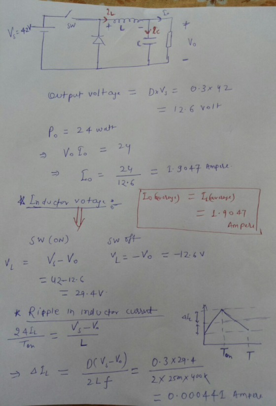
A buck converter is operating in the steady state with an input voltage of = 42 V dc, D = 0.3, ou...
A buck converter is operating in the steady state with an input voltage of = 42 V dc, D = 0.3, output power of 24 W, an inductance of 25 H and a switching frequency of 400 kHz. Draw the input current, inductor current, inductor voltage, and capacitor current waveforms. Assume the dc component of the inductor current flows through to the load and the ac component of the inductor current flows through the capacitor. Assume ideal circuit components.
Homework Answers

Add Answer to:
A buck converter is operating in the steady state with an input voltage of = 42 V dc, D = 0.3, ou...
Buck Converter Question Q3. A Buck converter is used to produce a regulated 10V, 5A DC...
 Buck Converter Question
Q3. A Buck converter is used to produce a regulated 10V, 5A DC power supply from a variable DC source with an nominal input voltage of Vin = 20V±5V. The Buck converter switches at 250kHz, and operates entirely in the continuous conduction mode. The output filter capacitance is C1.0uF 3.a. Draw the circuit topology for the Buck converter. Ensure that your circuit includes the input DC source, the output load resistance, the switching devices (i.e. MOSFET and...
Buck Converter Question
Q3. A Buck converter is used to produce a regulated 10V, 5A DC power supply from a variable DC source with an nominal input voltage of Vin = 20V±5V. The Buck converter switches at 250kHz, and operates entirely in the continuous conduction mode. The output filter capacitance is C1.0uF 3.a. Draw the circuit topology for the Buck converter. Ensure that your circuit includes the input DC source, the output load resistance, the switching devices (i.e. MOSFET and...
2.9 To reduce the switching harmonics present in the input current of a certain buck converter,...
 2.9 To reduce the switching harmonics present in the input current of a certain buck converter, an input filter consisting of inductor Li and capacitor Ci is added as shown in Fig. 2.32. Such filters are commonly used to meet regulations limiting conducted electromagnetic interference (EMI). For this problem, you may assume that all inductance and capacitance values are sufficiently large, such that all ripple magni- tudes are small CI Fig. 2.32 Addition of L-C input filter to buck converter,...
A buck converter is used to have low output voltage from the high input source to...
 A buck converter is used to have low output voltage from the high input source to low output voltage. The estimated power output is at 25 kW with the switching frequency of 25 kHz. Design the buck converter as by finding and following specifications consider the ripple of the output is set at 1% (i) Calculate the duty ratio of the buck converter (1 mark) (ii) Determine the minimum requirement for the inductor and the capacitor (5 marks) (iii) Determine...
A PV array with terminal voltage around 48 V under standard conditions is connected to a step-up dc-dc converter to supply a load at 120 V, 5 A. The input inductance is 8 mH with an internal resistanc...
A PV array with terminal voltage around 48 V under standard conditions is connected to a step-up dc-dc converter to supply a load at 120 V, 5 A. The input inductance is 8 mH with an internal resistance of 0.2 ohms, and the switching frequency is 5 kHz. Assuming ideal circuit components, calculate the duty ratio (k) and average input current (I1). Evaluate the maximum peak-to-peak input current ripple for the converter. If this current is limited to 2% of...
2. Renewable energy system requires a boost converter with input voltage variation of 18 V to 42 ...
 2. Renewable energy system requires a boost converter with input voltage variation of 18 V to 42 V (de) and gives output of 120 V at 0.6 kW. For the converter the switching frequency is set at 50 kHz. a) Find the operating duty cycle range for each switch of the converter0 marks b) 196 What is the inductor value which should keep inductor current variation below under all input voltages [30 marks] c) Find the capacitor value which should...
18 marks load with a power of 25.6 W.The cy f is 40kHz. sign a buck-boost converter to produce an output voltage of 16V a put voltage ripple must not exceed 1%. The dc input voltage is 24V. Th e swit...
 18 marks load with a power of 25.6 W.The cy f is 40kHz. sign a buck-boost converter to produce an output voltage of 16V a put voltage ripple must not exceed 1%. The dc input voltage is 24V. Th e switching frequen 121 a) the duty ratio b) Find the size of the inductor so that the maximum inductor current c) the size of the capacitor d) Assume L=1 00μH and the switching frequency fis variable. 141 121 Lma 10A...
+ VDS Consider the Buck DC-to-DC converter shown above. Assume it is operated at a switching...
 + VDS Consider the Buck DC-to-DC converter shown above. Assume it is operated at a switching frequency, f 25 KHz, with a duty cycle, D- 0.4 a) Given the sketch of the inductor current, i(t), shown below, sketch the waveforms for the input current, (t), the output current, i(t), the diode current, ip(), and the capacitor current, ict).Also, compute their average, RMS and peak values. (Note: Some useful formulas are provided on the last page) 10 5 t (s) (b)...
1. (35 points) Switch mode DC DC Converters. a. (15 points) Design a flyback DC/DC power converter to the following specifications. Assume ideal components Input Voltage Output Voltage Output Powe...
 1. (35 points) Switch mode DC DC Converters. a. (15 points) Design a flyback DC/DC power converter to the following specifications. Assume ideal components Input Voltage Output Voltage Output Power Switching frequency Maximum Current Ripple in the filter inductor Output ripple voltage: Continuous conduction 170 VDC 12 VDC 40 Watts 750 kHz 1.2 Amps Your answer should include a circuit diagram with each energy storage element labeled with its value. Label the transformer turns ratio.
1. (35 points) Switch mode...
1. (35 points) Switch mode DC DC Converters. a. (15 points) Design a flyback DC/DC power converter to the following specifications. Assume ideal components Input Voltage Output Voltage Output Power Switching frequency Maximum Current Ripple in the filter inductor Output ripple voltage: Continuous conduction 170 VDC 12 VDC 40 Watts 750 kHz 1.2 Amps Your answer should include a circuit diagram with each energy storage element labeled with its value. Label the transformer turns ratio.
1. (35 points) Switch mode...
Design a buck converter with the following specifications: Input voltage = 311 V Output voltage =...
Design a buck converter with the following specifications: Input voltage = 311 V Output voltage = 48 V Output voltage ripple = +/- 0.1% Maximum output current = 10 A Inductor current ripple = 5% Switching frequency = 100 kHz a) Select the inductor and the output capacitor and show a capture of the behaviour b) Calculate power losses assuming a rising time of 100 ns, a falling time of 100 ns, and Rdson = 10 mΩ. c) Calculate output...
Q5. 5.a. Sketch the circuit arrangement of a DC-DC boost (step up) converter, clearly labelling each...
 Q5. 5.a. Sketch the circuit arrangement of a DC-DC boost (step up) converter, clearly labelling each circuit element [4 тarks] [Refer to lecture notes] Sketch all significant operating waveforms for this converter for continuous conduction conditions over two switching periods, in particular showing 5.b. the voltage across the main switching device and the boost diode. [2 marks the voltage across the inductor [3 тarks] the current flowing through the inductor [3 marks [Refer to lecture notes] 5.c. The DC-DC boost...
 Buck Converter Question
Q3. A Buck converter is used to produce a regulated 10V, 5A DC power supply from a variable DC source with an nominal input voltage of Vin = 20V±5V. The Buck converter switches at 250kHz, and operates entirely in the continuous conduction mode. The output filter capacitance is C1.0uF 3.a. Draw the circuit topology for the Buck converter. Ensure that your circuit includes the input DC source, the output load resistance, the switching devices (i.e. MOSFET and...
Buck Converter Question
Q3. A Buck converter is used to produce a regulated 10V, 5A DC power supply from a variable DC source with an nominal input voltage of Vin = 20V±5V. The Buck converter switches at 250kHz, and operates entirely in the continuous conduction mode. The output filter capacitance is C1.0uF 3.a. Draw the circuit topology for the Buck converter. Ensure that your circuit includes the input DC source, the output load resistance, the switching devices (i.e. MOSFET and...
 2.9 To reduce the switching harmonics present in the input current of a certain buck converter, an input filter consisting of inductor Li and capacitor Ci is added as shown in Fig. 2.32. Such filters are commonly used to meet regulations limiting conducted electromagnetic interference (EMI). For this problem, you may assume that all inductance and capacitance values are sufficiently large, such that all ripple magni- tudes are small CI Fig. 2.32 Addition of L-C input filter to buck converter,...
 A buck converter is used to have low output voltage from the high input source to low output voltage. The estimated power output is at 25 kW with the switching frequency of 25 kHz. Design the buck converter as by finding and following specifications consider the ripple of the output is set at 1% (i) Calculate the duty ratio of the buck converter (1 mark) (ii) Determine the minimum requirement for the inductor and the capacitor (5 marks) (iii) Determine...
 2. Renewable energy system requires a boost converter with input voltage variation of 18 V to 42 V (de) and gives output of 120 V at 0.6 kW. For the converter the switching frequency is set at 50 kHz. a) Find the operating duty cycle range for each switch of the converter0 marks b) 196 What is the inductor value which should keep inductor current variation below under all input voltages [30 marks] c) Find the capacitor value which should...
 18 marks load with a power of 25.6 W.The cy f is 40kHz. sign a buck-boost converter to produce an output voltage of 16V a put voltage ripple must not exceed 1%. The dc input voltage is 24V. Th e switching frequen 121 a) the duty ratio b) Find the size of the inductor so that the maximum inductor current c) the size of the capacitor d) Assume L=1 00μH and the switching frequency fis variable. 141 121 Lma 10A...
 + VDS Consider the Buck DC-to-DC converter shown above. Assume it is operated at a switching frequency, f 25 KHz, with a duty cycle, D- 0.4 a) Given the sketch of the inductor current, i(t), shown below, sketch the waveforms for the input current, (t), the output current, i(t), the diode current, ip(), and the capacitor current, ict).Also, compute their average, RMS and peak values. (Note: Some useful formulas are provided on the last page) 10 5 t (s) (b)...
 1. (35 points) Switch mode DC DC Converters. a. (15 points) Design a flyback DC/DC power converter to the following specifications. Assume ideal components Input Voltage Output Voltage Output Power Switching frequency Maximum Current Ripple in the filter inductor Output ripple voltage: Continuous conduction 170 VDC 12 VDC 40 Watts 750 kHz 1.2 Amps Your answer should include a circuit diagram with each energy storage element labeled with its value. Label the transformer turns ratio.
1. (35 points) Switch mode...
1. (35 points) Switch mode DC DC Converters. a. (15 points) Design a flyback DC/DC power converter to the following specifications. Assume ideal components Input Voltage Output Voltage Output Power Switching frequency Maximum Current Ripple in the filter inductor Output ripple voltage: Continuous conduction 170 VDC 12 VDC 40 Watts 750 kHz 1.2 Amps Your answer should include a circuit diagram with each energy storage element labeled with its value. Label the transformer turns ratio.
1. (35 points) Switch mode...
 Q5. 5.a. Sketch the circuit arrangement of a DC-DC boost (step up) converter, clearly labelling each circuit element [4 тarks] [Refer to lecture notes] Sketch all significant operating waveforms for this converter for continuous conduction conditions over two switching periods, in particular showing 5.b. the voltage across the main switching device and the boost diode. [2 marks the voltage across the inductor [3 тarks] the current flowing through the inductor [3 marks [Refer to lecture notes] 5.c. The DC-DC boost...
Most questions answered within 3 hours.
-
Which of the hypothesis tests listed below is a
two-tailed test? Select all correct answers.
Select...
asked 32 seconds ago -
Solve following questions. ?= √?.M is your house value. If there
is a flood, your house...
asked 3 minutes ago -
Critical Thinking: Assume an economy that has a total
population of 290 million people of which...
asked 4 minutes ago -
Accounts receivable subsidiary ledger, schedule of
accounts receivable lo c1. Vali company recorded the following
selected...
asked 13 minutes ago -
Connell performed a series of studies to understand what limits
the distribution of barnacle species within...
asked 17 minutes ago -
I throw a die with 6 sides. Consider the events, A=uneven and
B=prime number. Find the...
asked 20 minutes ago -
Common-Sized Income Statement
Revenue and expense data for the current calendar year for
Tannenhill Company and...
asked 38 minutes ago -
Find the present value of an annuity due that pays $3000 at the
beginning of each...
asked 47 minutes ago -
A reaction is second order with respect to [A] and half order
with respect to [B]....
asked 46 minutes ago -
In your groups, list the international actors you would expect
to encounter in an emergency logistics...
asked 1 hour ago -
When one molecule of methane combusts with oxygen, 5.74 X
10-21 J is released as heat....
asked 1 hour ago -
Required information
[The following information applies to the questions
displayed below.]
Satellite Systems modified its model...
asked 1 hour ago