

Homework Answers


Add Answer to:
Derive a solution for the voltage across the capacitor C1 in Fig. 1 as a function...
What are the values of v(t) at times 12.5, 37.5, 62.5, 87.5, and 112.5 ms time...
 What are the values of v(t) at times 12.5, 37.5, 62.5, 87.5, and
112.5 ms
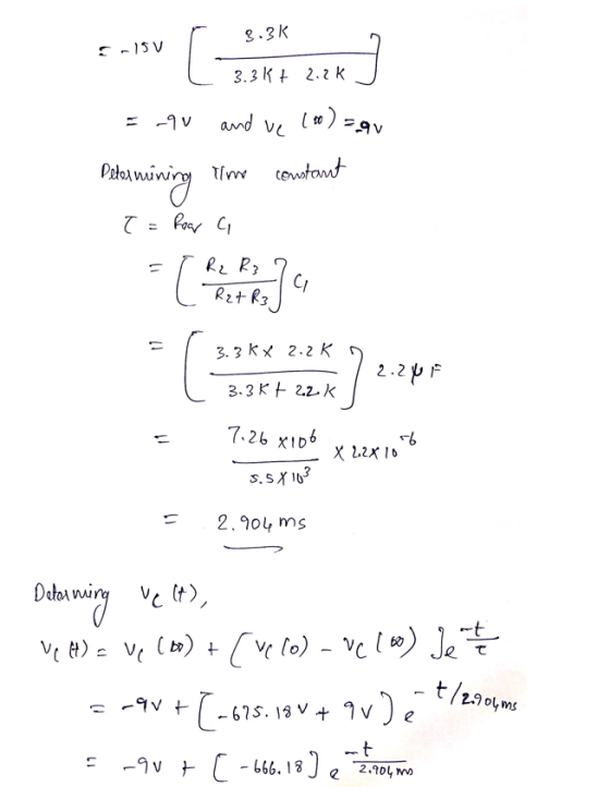
time from t 0 ms to t 125 ms if the switches are controlled as shown in Fig. 2 The initial capacitor voltage is -9 V. Show all of your work. S4 R3 R1 S1 C1 + +R2 V2+ Fig. 1. Switched RC it. V19 V, V2-15 V, R1 4.7 kQ, R2 3.3 kQ, R3 kQ, C1 2.2 ?F. 2.2
What are the values of v(t) at times 12.5, 37.5, 62.5, 87.5, and
112.5 ms
time from t 0 ms to t 125 ms if the switches are controlled as shown in Fig. 2 The initial capacitor voltage is -9 V. Show all of your work. S4 R3 R1 S1 C1 + +R2 V2+ Fig. 1. Switched RC it. V19 V, V2-15 V, R1 4.7 kQ, R2 3.3 kQ, R3 kQ, C1 2.2 ?F. 2.2
Derive a model of the voltage of capacitor-1 (ve(t). The circuit is switched on after t-o. Ic Ie ...
 Derive a model of the voltage of capacitor-1 (ve(t). The circuit is switched on after t-o. Ic Ie R1 R3 Vs C1 일사 C2な
Derive a model of the voltage of capacitor-1 (ve(t). The circuit is switched on after t-o. Ic Ie R1 R3 Vs C1 일사 C2な
Derive a model of the voltage of capacitor-1 (ve(t). The circuit is switched on after t-o. Ic Ie R1 R3 Vs C1 일사 C2な
1. Consider this circuit with resistors and capacitors. The R2 battery V1 has a voltage of...
 1. Consider this circuit with resistors and capacitors. The R2 battery V1 has a voltage of 9 V, the resistors R1 and R2 have values of 100 Ω and 50 Ω, and the capacitor C1 has a value of 100 nF. Initially, the switches S1 and S2 are open. S2 (10 points) Once we close S1, what will the voltage across Rl and Cl be? How much current initially flows around the closed loop? (10 points) The current in part...
Phasor-Domain Analysis Techniques (7-9) 7.4 The circuit of Figure 7.5 operates at 1 kHz. Determine the...
 Phasor-Domain Analysis Techniques (7-9) 7.4 The circuit of Figure 7.5 operates at 1 kHz. Determine the node voltages VA and VB Use these component values: 3.3 k2 and R3 = 2.2 k 4.7 k, R2 Ri C1 0.047 Fand C2 0.1 F Vi 9/0° V and V2 = 3/ - 90° V VA VB R3 R2 R1 ww :C2 = C1 V2 V1
For the circuit shown below: Preview In terms of Vo, R1, R2, R3, R4 C1, t, and s what is the time domain equation for the voltage at node out? Preview and s what is the s-domain equation the voltage...
 For the circuit shown below: Preview In terms of Vo, R1, R2, R3, R4 C1, t, and s what is the time domain equation for the voltage at node out? Preview and s what is the s-domain equation the voltage at node out? In terms of Vo, RI, R2, R3,R4, C1, t, Preview and s what is the equation for τ? In terms ofVo, RI, R2, R3, R4, Cl, t, Ifthe voltage V1 at time-0 is 3 V RI=4 kQ,...
For the circuit shown below: In terms of Vo, R1, R2, R3, R4, C1, t, and s what is the time domain...
 For the circuit shown below: In terms of Vo, R1, R2, R3, R4, C1, t, and s what is the time domain equation for the voltage at node out? Preview In terms of Vo, R1, R2, ,R3, R4, C1, t, and s what is the s-domain equation for voltage at node out? In terms of Vo, RI, R2, R3, R4, CI, t, and s what is the equation for τ? If the voltage V1 at time-0 is 1 V R1-1...
What is the ratio of the voltage V1 across capacitor C1 in (Figure 1) to the...
 What is the ratio of the
voltage V1 across capacitor C1 in (Figure 1) to the voltage V2
across capacitor C2? Suppose that C2 = 2.4μF
What is the ratio of the voltage V1 across capacitor C1 in (Figure 11 to the voltage V2 across capacitor C2?. Suppose that C2 = 2.4 mu F Express your answer using two significant figures.
What is the ratio of the
voltage V1 across capacitor C1 in (Figure 1) to the voltage V2
across capacitor C2? Suppose that C2 = 2.4μF
What is the ratio of the voltage V1 across capacitor C1 in (Figure 11 to the voltage V2 across capacitor C2?. Suppose that C2 = 2.4 mu F Express your answer using two significant figures.
(5) Capacitor and Transient Analysis 7 marks Fig. P-5A shows a switching circuit with switches Si...
 (5) Capacitor and Transient Analysis 7 marks Fig. P-5A shows a switching circuit with switches Si and S2 that are opened and closed periodically. Fig. P-5B shows the steady state waveform of the output voltage V.(t). Compute the steady state values of V1 and V2. R: Vo(t) Vo(t) Vot 5V V2 --- -- 1kΩ 1uF C Vi Ve 5V Fig. P-5A Fig. P-5B (not to scale) (5a) 3 marks Let the initial voltage of the capacitor be V.(O)= V1. The...
For the circuit shown below In terms of Vo. RI. R2, R3. R4 Cİ.t and s what is the time domain equation for the voltage at node out? Preview In terms of Vo, R1, R2, R3 R4, C1,t, and s what is the freq...
 For the circuit shown below In terms of Vo. RI. R2, R3. R4 Cİ.t and s what is the time domain equation for the voltage at node out? Preview In terms of Vo, R1, R2, R3 R4, C1,t, and s what is the frequency domain equation the voltage at node out? Preview In terms of Vo. R1. R2. R3. R4. Cl.t. and s what is the equation for t? Preview Ifthe voltage vi at tune-0 is 3 V RI"? kQ....
Ri Sw Sw2R (a) Circuit Swi Closed + Open T t (ms) 10 20 30 40...
 Ri Sw Sw2R (a) Circuit Swi Closed + Open T t (ms) 10 20 30 40 50 Sw2 Closed (ms) 10 20 30 40 50 Figure m5.3 Voltage waveform for Problem m5.3. m5.3 Response of the RC Circuit: Figure m5.3(a) shows a resistor-capacitor circuit with a pair of switches and Fig. m5.3(b) shows the switch opening-closing behavior a function of time. The initial capacitor voltage is as -9 V. Component values are R1-10k. R2-3.3 kg2. (a) Determine the equation that...
 What are the values of v(t) at times 12.5, 37.5, 62.5, 87.5, and
112.5 ms
time from t 0 ms to t 125 ms if the switches are controlled as shown in Fig. 2 The initial capacitor voltage is -9 V. Show all of your work. S4 R3 R1 S1 C1 + +R2 V2+ Fig. 1. Switched RC it. V19 V, V2-15 V, R1 4.7 kQ, R2 3.3 kQ, R3 kQ, C1 2.2 ?F. 2.2
What are the values of v(t) at times 12.5, 37.5, 62.5, 87.5, and
112.5 ms
time from t 0 ms to t 125 ms if the switches are controlled as shown in Fig. 2 The initial capacitor voltage is -9 V. Show all of your work. S4 R3 R1 S1 C1 + +R2 V2+ Fig. 1. Switched RC it. V19 V, V2-15 V, R1 4.7 kQ, R2 3.3 kQ, R3 kQ, C1 2.2 ?F. 2.2
 Derive a model of the voltage of capacitor-1 (ve(t). The circuit is switched on after t-o. Ic Ie R1 R3 Vs C1 일사 C2な
Derive a model of the voltage of capacitor-1 (ve(t). The circuit is switched on after t-o. Ic Ie R1 R3 Vs C1 일사 C2な
Derive a model of the voltage of capacitor-1 (ve(t). The circuit is switched on after t-o. Ic Ie R1 R3 Vs C1 일사 C2な
 1. Consider this circuit with resistors and capacitors. The R2 battery V1 has a voltage of 9 V, the resistors R1 and R2 have values of 100 Ω and 50 Ω, and the capacitor C1 has a value of 100 nF. Initially, the switches S1 and S2 are open. S2 (10 points) Once we close S1, what will the voltage across Rl and Cl be? How much current initially flows around the closed loop? (10 points) The current in part...
 Phasor-Domain Analysis Techniques (7-9) 7.4 The circuit of Figure 7.5 operates at 1 kHz. Determine the node voltages VA and VB Use these component values: 3.3 k2 and R3 = 2.2 k 4.7 k, R2 Ri C1 0.047 Fand C2 0.1 F Vi 9/0° V and V2 = 3/ - 90° V VA VB R3 R2 R1 ww :C2 = C1 V2 V1
 For the circuit shown below: Preview In terms of Vo, R1, R2, R3, R4 C1, t, and s what is the time domain equation for the voltage at node out? Preview and s what is the s-domain equation the voltage at node out? In terms of Vo, RI, R2, R3,R4, C1, t, Preview and s what is the equation for τ? In terms ofVo, RI, R2, R3, R4, Cl, t, Ifthe voltage V1 at time-0 is 3 V RI=4 kQ,...
 For the circuit shown below: In terms of Vo, R1, R2, R3, R4, C1, t, and s what is the time domain equation for the voltage at node out? Preview In terms of Vo, R1, R2, ,R3, R4, C1, t, and s what is the s-domain equation for voltage at node out? In terms of Vo, RI, R2, R3, R4, CI, t, and s what is the equation for τ? If the voltage V1 at time-0 is 1 V R1-1...
 What is the ratio of the
voltage V1 across capacitor C1 in (Figure 1) to the voltage V2
across capacitor C2? Suppose that C2 = 2.4μF
What is the ratio of the voltage V1 across capacitor C1 in (Figure 11 to the voltage V2 across capacitor C2?. Suppose that C2 = 2.4 mu F Express your answer using two significant figures.
What is the ratio of the
voltage V1 across capacitor C1 in (Figure 1) to the voltage V2
across capacitor C2? Suppose that C2 = 2.4μF
What is the ratio of the voltage V1 across capacitor C1 in (Figure 11 to the voltage V2 across capacitor C2?. Suppose that C2 = 2.4 mu F Express your answer using two significant figures.
 (5) Capacitor and Transient Analysis 7 marks Fig. P-5A shows a switching circuit with switches Si and S2 that are opened and closed periodically. Fig. P-5B shows the steady state waveform of the output voltage V.(t). Compute the steady state values of V1 and V2. R: Vo(t) Vo(t) Vot 5V V2 --- -- 1kΩ 1uF C Vi Ve 5V Fig. P-5A Fig. P-5B (not to scale) (5a) 3 marks Let the initial voltage of the capacitor be V.(O)= V1. The...
 For the circuit shown below In terms of Vo. RI. R2, R3. R4 Cİ.t and s what is the time domain equation for the voltage at node out? Preview In terms of Vo, R1, R2, R3 R4, C1,t, and s what is the frequency domain equation the voltage at node out? Preview In terms of Vo. R1. R2. R3. R4. Cl.t. and s what is the equation for t? Preview Ifthe voltage vi at tune-0 is 3 V RI"? kQ....
 Ri Sw Sw2R (a) Circuit Swi Closed + Open T t (ms) 10 20 30 40 50 Sw2 Closed (ms) 10 20 30 40 50 Figure m5.3 Voltage waveform for Problem m5.3. m5.3 Response of the RC Circuit: Figure m5.3(a) shows a resistor-capacitor circuit with a pair of switches and Fig. m5.3(b) shows the switch opening-closing behavior a function of time. The initial capacitor voltage is as -9 V. Component values are R1-10k. R2-3.3 kg2. (a) Determine the equation that...
Most questions answered within 3 hours.
-
1. Which of the following is NOT an argument that McMahan uses
to show that jus...
asked 14 minutes ago -
A crate slides up a frictionless slope. At the end of 3 seconds
its velocity is...
asked 31 minutes ago -
Use the following information to answer the next seven
questions.
Suppose there are three potential states...
asked 27 minutes ago -
If we only have interstitial and substitutional diffusion, then
what do we consider the process of...
asked 43 minutes ago -
You look at yourself in a shiny 9.6-cm-diameter Christmas tree
ball.
If your face is 21.0...
asked 45 minutes ago -
If we were to measure the relaxation time of a muscle after
undergoing tetanus compared to...
asked 45 minutes ago -
4CO(g) + 8H2(g) -----> 3CH4(g) +
CO2(g) + 2H2O(l)
Use the following data as needed to...
asked 48 minutes ago -
without using map
1. Write a C++ program to find out the top 10 words in...
asked 1 hour ago -
1)Calculate the percent ionization of a
0.330 M solution of hypochlorous
acid.
% Ionization = %...
asked 1 hour ago -
1a) How many grams of K2SO4 are in 250mL
of 0.11 M K2SO4 solution?
_____ g...
asked 55 minutes ago -
The vapor pressure of a solution containing 38.7 g glycerin
(C3H8O3) in 146.2 g ethanol (C2H5OH)...
asked 1 hour ago -
A physics major is cooking breakfast when he notices that the
frictional force between the steel...
asked 1 hour ago