

Homework Answers

Add Answer to:
Referring to the circuit in Figure 2 and the corresponding function table in Table 5 on...
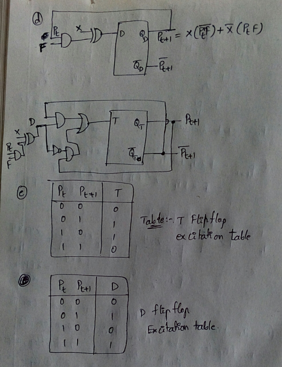
PROBLEM 3 (16 PTS) ▪ With a D flip flop and logic gates, sketch the circuit...
 PROBLEM 3 (16 PTS) ▪ With a D
flip flop and logic gates, sketch the circuit whose excitation
equation is given by:
PROBLEM 3 (16 PTS) • With a D flip flop and logic gates, sketch the circuit whose excitation equation is given by: Qit+1) + y + Q(t) + y(t) (4 pts) • Complete the timing diagram of the circuit whose VHDL description is shown below. Also, get the excitation equation for q. library ieee: elsaf (cll'event and clk...
PROBLEM 3 (16 PTS) ▪ With a D
flip flop and logic gates, sketch the circuit whose excitation
equation is given by:
PROBLEM 3 (16 PTS) • With a D flip flop and logic gates, sketch the circuit whose excitation equation is given by: Qit+1) + y + Q(t) + y(t) (4 pts) • Complete the timing diagram of the circuit whose VHDL description is shown below. Also, get the excitation equation for q. library ieee: elsaf (cll'event and clk...
a) (5 marks) Explain the difference between a latch, a gated latch and a flip flop....
 a) (5 marks) Explain the difference between a latch, a gated latch and a flip flop. b) (5 marks) A gated SR latch has the following schematic diagram CLK a) Draw a timing diagram showing the Q and Q outputs for the following sequence of inputs: CLK R Assume that the initial state of the outputs is Q 0 and Q 1 c) (5 marks) Draw a schematic diagram for a rising edge-triggered master-slave D flip- flop built using two...
1. Find the Boolean expression of the truth table. Then simplify it and convert it into...
 1. Find the Boolean expression of the truth table. Then simplify it and convert it into the least amount of logic gates possible. AB Output 100 011 101 2. Find the POS form of the Boolean expressions below. Find the truth table and logic minimization method of it. Show its gate level implementation, and show the same gate level implementation using only NAND gates. A(X,Y,Z)= m(0,2,4,6) B(X,Y,2)={m(0,4,5) 3. Create a J-k Flip Flop using a D-Flip Flop. Show its truth...
Study the following circuit and corresponding waveforms: a) D Q Clock CLK Q Undefined 01 02...
 Study the following circuit and corresponding waveforms: a) D Q Clock CLK Q Undefined 01 02 Undefined Q Undefined Undefined Undefined Identify the waveforms that correspond to Qa, Qb and Qc. Provide the name of the components that produce Qa, Qb and Qc. (Note: one answer is none of the above.) (6 marks) b) Study the following circuit: D D D CLK CLK CLK CLK Explain why this will not implement a shift register. Your answer should include a waveform...
Q2) The following is a Boolean expression of a Combinational Logic Circuit. Construct the truth table...
 Q2) The following is a Boolean expression of a Combinational Logic Circuit. Construct the truth table and a Combinational Logic circuit using AND, OR and NOT logic gates for the Boolean expression. Redraw the logic circuit using only NAND gates. 19 Marks) X = A B C +ABC + ABC
NAND Problem 3 (30 points) Consider the circuit shown alongside. Notice that there is one A input...
 NAND Problem 3 (30 points) Consider the circuit shown alongside. Notice that there is one A input x and one output. FULL ADDER XOR (a) [5 points] Determine the B Q Cout Clk flip-flop input equations and xin the output z in terms of the present states A, B and input variable x in other words 4-1 compute T, J, K and z. MUX (b) [10 points] Use the above 1 equations to derive the state- 01 table. Assume the...
14. Design a cyclic counter that produces the binary sequence 0, 2, 3,1. o..if the control signal...
 14?
14. Design a cyclic counter that produces the binary sequence 0, 2, 3,1. o..if the control signal X is 0 but produces the binary sequence 0, 1,3,2.0, if the control signal X is1.Use D flip-flops. (a) Draw the state diagram; (6 points (b) Draw the input, present state-next state, excitation table: (6 points) (c) Derive the minimal SOP expressions for the D inputs of the flip-flops using K-maps. Draw the logic circuit realization of the counter, using only NAND...
14?
14. Design a cyclic counter that produces the binary sequence 0, 2, 3,1. o..if the control signal X is 0 but produces the binary sequence 0, 1,3,2.0, if the control signal X is1.Use D flip-flops. (a) Draw the state diagram; (6 points (b) Draw the input, present state-next state, excitation table: (6 points) (c) Derive the minimal SOP expressions for the D inputs of the flip-flops using K-maps. Draw the logic circuit realization of the counter, using only NAND...
(a) Design an asynchronous Binary Coded Decimal (BCD) count-up counter using JK flip-flops. Draw the counter circuit clearly showing the configuration of the JK flip-flops and the necessary logic gat...
 (a) Design an asynchronous Binary Coded Decimal (BCD) count-up counter using JK flip-flops. Draw the counter circuit clearly showing the configuration of the JK flip-flops and the necessary logic gate(s). Sketch the input and output waveforms of this counter (7 Marks) (b) The binary up/down counter for a cargo lift controller in a 7-storey building has an up-down (UID) control input and a buzzer output (B). The buzzer will sound B 1) when the lift is at level 1 or...
(e) Suppose that for the circuit of Figure 11-21, new semiconductor technol- ogy has allowed us...
 (e) Suppose that for the circuit of Figure 11-21, new semiconductor technol- ogy has allowed us to improve the delays and setup times. The propagation delay of the new inverter is 1.5 ns, and the propagation delay and setup times of the new flip-flop are 3.5 ns and 2 ns, respectively. What is the short- est clock period for the circuit of Figure 11-21(a) which will not violate the timing constraints? Setup time 3 si CLK FIGURE 11-21 Determination of...
Q6. a) Write the output expression for the circuit shown in the figure. b) Develop truth...
 Q6. a) Write the output expression for the circuit shown in the figure. b) Develop truth table for the circuit. (1 Mark) (4 Marks) A B C 13 X D Fig.2 07 [5] a) Minimize the following logic function using K-Map. b) Implement the minimized expression using basic gates. (3 Marks) (2 Marks) F(A,B,C,D) = (0,2,5,7,8,10,13,15) Q8 a) Write the output expression of the logic circuit shown in the figure. b) Minimize the expression using Boolean laws and theorems. C)...
 PROBLEM 3 (16 PTS) ▪ With a D
flip flop and logic gates, sketch the circuit whose excitation
equation is given by:
PROBLEM 3 (16 PTS) • With a D flip flop and logic gates, sketch the circuit whose excitation equation is given by: Qit+1) + y + Q(t) + y(t) (4 pts) • Complete the timing diagram of the circuit whose VHDL description is shown below. Also, get the excitation equation for q. library ieee: elsaf (cll'event and clk...
PROBLEM 3 (16 PTS) ▪ With a D
flip flop and logic gates, sketch the circuit whose excitation
equation is given by:
PROBLEM 3 (16 PTS) • With a D flip flop and logic gates, sketch the circuit whose excitation equation is given by: Qit+1) + y + Q(t) + y(t) (4 pts) • Complete the timing diagram of the circuit whose VHDL description is shown below. Also, get the excitation equation for q. library ieee: elsaf (cll'event and clk...
 a) (5 marks) Explain the difference between a latch, a gated latch and a flip flop. b) (5 marks) A gated SR latch has the following schematic diagram CLK a) Draw a timing diagram showing the Q and Q outputs for the following sequence of inputs: CLK R Assume that the initial state of the outputs is Q 0 and Q 1 c) (5 marks) Draw a schematic diagram for a rising edge-triggered master-slave D flip- flop built using two...
 1. Find the Boolean expression of the truth table. Then simplify it and convert it into the least amount of logic gates possible. AB Output 100 011 101 2. Find the POS form of the Boolean expressions below. Find the truth table and logic minimization method of it. Show its gate level implementation, and show the same gate level implementation using only NAND gates. A(X,Y,Z)= m(0,2,4,6) B(X,Y,2)={m(0,4,5) 3. Create a J-k Flip Flop using a D-Flip Flop. Show its truth...
 Study the following circuit and corresponding waveforms: a) D Q Clock CLK Q Undefined 01 02 Undefined Q Undefined Undefined Undefined Identify the waveforms that correspond to Qa, Qb and Qc. Provide the name of the components that produce Qa, Qb and Qc. (Note: one answer is none of the above.) (6 marks) b) Study the following circuit: D D D CLK CLK CLK CLK Explain why this will not implement a shift register. Your answer should include a waveform...
 Q2) The following is a Boolean expression of a Combinational Logic Circuit. Construct the truth table and a Combinational Logic circuit using AND, OR and NOT logic gates for the Boolean expression. Redraw the logic circuit using only NAND gates. 19 Marks) X = A B C +ABC + ABC
 NAND Problem 3 (30 points) Consider the circuit shown alongside. Notice that there is one A input x and one output. FULL ADDER XOR (a) [5 points] Determine the B Q Cout Clk flip-flop input equations and xin the output z in terms of the present states A, B and input variable x in other words 4-1 compute T, J, K and z. MUX (b) [10 points] Use the above 1 equations to derive the state- 01 table. Assume the...
 14?
14. Design a cyclic counter that produces the binary sequence 0, 2, 3,1. o..if the control signal X is 0 but produces the binary sequence 0, 1,3,2.0, if the control signal X is1.Use D flip-flops. (a) Draw the state diagram; (6 points (b) Draw the input, present state-next state, excitation table: (6 points) (c) Derive the minimal SOP expressions for the D inputs of the flip-flops using K-maps. Draw the logic circuit realization of the counter, using only NAND...
14?
14. Design a cyclic counter that produces the binary sequence 0, 2, 3,1. o..if the control signal X is 0 but produces the binary sequence 0, 1,3,2.0, if the control signal X is1.Use D flip-flops. (a) Draw the state diagram; (6 points (b) Draw the input, present state-next state, excitation table: (6 points) (c) Derive the minimal SOP expressions for the D inputs of the flip-flops using K-maps. Draw the logic circuit realization of the counter, using only NAND...
 (a) Design an asynchronous Binary Coded Decimal (BCD) count-up counter using JK flip-flops. Draw the counter circuit clearly showing the configuration of the JK flip-flops and the necessary logic gate(s). Sketch the input and output waveforms of this counter (7 Marks) (b) The binary up/down counter for a cargo lift controller in a 7-storey building has an up-down (UID) control input and a buzzer output (B). The buzzer will sound B 1) when the lift is at level 1 or...
 (e) Suppose that for the circuit of Figure 11-21, new semiconductor technol- ogy has allowed us to improve the delays and setup times. The propagation delay of the new inverter is 1.5 ns, and the propagation delay and setup times of the new flip-flop are 3.5 ns and 2 ns, respectively. What is the short- est clock period for the circuit of Figure 11-21(a) which will not violate the timing constraints? Setup time 3 si CLK FIGURE 11-21 Determination of...
 Q6. a) Write the output expression for the circuit shown in the figure. b) Develop truth table for the circuit. (1 Mark) (4 Marks) A B C 13 X D Fig.2 07 [5] a) Minimize the following logic function using K-Map. b) Implement the minimized expression using basic gates. (3 Marks) (2 Marks) F(A,B,C,D) = (0,2,5,7,8,10,13,15) Q8 a) Write the output expression of the logic circuit shown in the figure. b) Minimize the expression using Boolean laws and theorems. C)...
Most questions answered within 3 hours.
-
Nadia Corporation adjusts its debt so that its interest coverage
(EBIT/Interest) remains constant at 3. Nadia’s...
asked 25 seconds ago -
In a clinical trial, 20 out of 600 patients taking a
prescription drug complained of flulike...
asked 6 minutes ago -
7. How many types of nuclear processes can produce energy? 8.
How many types of radioactive...
asked 9 minutes ago -
For both the Sn2 and Sn1 reaction
conditions:
Structure | Rxn (Y/N) at room T° Rxn...
asked 10 minutes ago -
11. In cell N2, enter a formula using the IF function and a
structured reference to...
asked 10 minutes ago -
There is X-linked mutations in flies in this example. You need
to determine the inheritence pattern...
asked 12 minutes ago -
1) There is a 5.0 μC charge at each of 3 corners of a square
(each...
asked 23 minutes ago -
A study of 420,095 cell phone users found that
134 of them developed cancer of the...
asked 27 minutes ago -
2.50 g of NH4Cl is added to 12.9 g of water. Calculate the
molality of the...
asked 29 minutes ago -
Part 1
(a) Calculate the pH at 25°C of a 0.10 M solution of a
weak...
asked 31 minutes ago -
1-Calculate the mass in grams of 2.55 moles of KCl
2- Calculate how many moles are...
asked 59 minutes ago -
Bright Sun, Inc. sold an issue of 30-year $1,000 par value bonds
to the public. The...
asked 53 minutes ago