
Homework Answers

Add Answer to:
Take that the 80 kN load may be applied at any point on the circumference of...
A load of 80 Kn is applied to a steel bar system as shown. Determine the...
 A load of 80 Kn is applied to a steel bar system as shown.
Determine the shear stress applied to plate D and the normal effort
that the C-bar supports
400 mm Placa D 80 kN. 30 mm 70 mm 600 mm
A load of 80 Kn is applied to a steel bar system as shown.
Determine the shear stress applied to plate D and the normal effort
that the C-bar supports
400 mm Placa D 80 kN. 30 mm 70 mm 600 mm
A load P is supported as shown by a steel pin that has been inserted in...
 A load P is supported as shown by a steel pin that has been inserted in a short wooden member hanging from the ceiling. The ultimate strength of the wood used is 60 MPa in tension and 7.5 MPa in shear, while the ultimate strength of the steel is 145 MPa in shear. The diameter of the pin is d= 18 mm and the magnitude of the load is P= 20 KN. NOTE: This is a multi-part question. Once an...
2A. A load of 85 kN is applied to the system of linkages at point B....
 2A. A load of 85 kN is applied to the system of linkages at point B. All linkage components are made of Aluminum (E 70 GPa) Each linkage member has a cross- section as shown below. The pin at D is in single shear, and has a diameter of 40.0 mm. (a). Find the average shear stress in (b). Find the average normal stress (c) Find the extension/contraction (d) Find the average normal stress pin D at the midpoint of...
Two forces 3 kN and 2.5 kN are applied to the machine component ABD as shown...
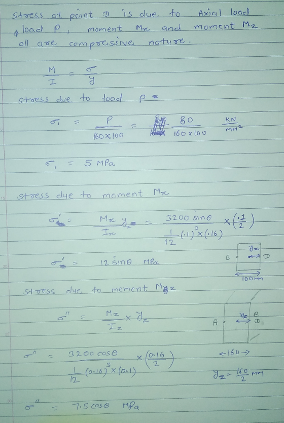
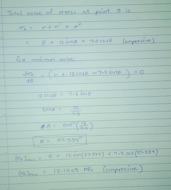
 Two forces 3 kN and 2.5 kN are applied to the machine component ABD as shown in Figure 3. Given that the cross section containing the point H is a rectangle of dimensions 20mm x 10mm, determine the following a. Draw the free body diagram at H, and indicate the reaction forces/moments. b. Indicate the state of stress at Point H and the components of stress in the proper directions on a stress block or stress element (as indicated in...
NOTE: This is a multi-part question. Once an answer is submitted, you will be unable to...
 NOTE: This is a multi-part question. Once an answer is submitted, you will be unable to return to this part. A pulley is shown with other components of the frame. 125 mm 75 mm 300mm- 300mm Knowing that the pulley has a radius of 75 mm and the load Pis 240 N determine the components of the reactions at A and B The components of the reaction at Aare Ax= N. A, The components of the reaction at Bare By...
A vertical load P = 150 kN is applied to a circular solid shaft which in turn is supported by a circular end cap as sho...
 A vertical load P = 150 kN is applied to a circular solid shaft which in turn is supported by a circular end cap as shown below. Both members are made of steel with allowable normal stress = 160 MPa, allowable shear stress 100 MPa, and allowable bearing stress 200 MPa. Determine the minimum required diameter of the solid shaft, and the minimum required outer diameter and thickness of the circular end plate. P 150 kN ds d 30 mm...
Required information In the truss shown, members AC and AD consist of rods made of the...
 Required information In the truss shown, members AC and AD consist of rods made of the same metal alloy. AC is of 25-mm diameter and the ultimate load for that rod is 385 kN. NOTE: This is a multi-part question. Once an answer is submitted, you will be unable to return to this part. 1.5 m B 3 m 3 m 48 kN 48 kN Determine the required diameter of AD if it is desired that both rods have the...
Detemine the tension in cable BC in kN Required information NOTE: This is a multi-part question....
 Detemine the tension in cable BC in kN
Required information NOTE: This is a multi-part question. Once an answer is submitted, you will be unable to return to this part. Two cables are tied together at Cand are loaded as shown. Given: WE 175 kg. 30 Determine the tension in cable BC. The tension in cable BC is kN.
Detemine the tension in cable BC in kN
Required information NOTE: This is a multi-part question. Once an answer is submitted, you will be unable to return to this part. Two cables are tied together at Cand are loaded as shown. Given: WE 175 kg. 30 Determine the tension in cable BC. The tension in cable BC is kN.
Required information NOTE: This is a multi-part question. Once an answer is submitted, you will b...
 2 part problem, thanks!
Required information NOTE: This is a multi-part question. Once an answer is submitted, you will be unable to return to this part The pin at Bis attached to member ABD and can slide freely along the slot cut in the fixed plate. The angular velocity of arm DE is 3.5 rad/s clockwise at the instant shown. 200 mn 120 mm 30 160 am Determine the angular velocity of member ABD. (You must provide an answer before...
2 part problem, thanks!
Required information NOTE: This is a multi-part question. Once an answer is submitted, you will be unable to return to this part The pin at Bis attached to member ABD and can slide freely along the slot cut in the fixed plate. The angular velocity of arm DE is 3.5 rad/s clockwise at the instant shown. 200 mn 120 mm 30 160 am Determine the angular velocity of member ABD. (You must provide an answer before...
Required information NOTE: This is a multi-part question. Once an answer is submitted, you will be...
 Required information NOTE: This is a multi-part question. Once an answer is submitted, you will be unable to return to this part A frame and a loading are shown. Note that α-9ợ 300 mm 200 mm 75 mm 400 mm 200 mm Determine the internal forces at point Jwhen P 1.8 kN. The axial force is The shear force is The bending moment is kN-m (Click to se kN (Click to select) kN (Click to select) lech (Click to select)...
 A load of 80 Kn is applied to a steel bar system as shown.
Determine the shear stress applied to plate D and the normal effort
that the C-bar supports
400 mm Placa D 80 kN. 30 mm 70 mm 600 mm
A load of 80 Kn is applied to a steel bar system as shown.
Determine the shear stress applied to plate D and the normal effort
that the C-bar supports
400 mm Placa D 80 kN. 30 mm 70 mm 600 mm
 A load P is supported as shown by a steel pin that has been inserted in a short wooden member hanging from the ceiling. The ultimate strength of the wood used is 60 MPa in tension and 7.5 MPa in shear, while the ultimate strength of the steel is 145 MPa in shear. The diameter of the pin is d= 18 mm and the magnitude of the load is P= 20 KN. NOTE: This is a multi-part question. Once an...
 2A. A load of 85 kN is applied to the system of linkages at point B. All linkage components are made of Aluminum (E 70 GPa) Each linkage member has a cross- section as shown below. The pin at D is in single shear, and has a diameter of 40.0 mm. (a). Find the average shear stress in (b). Find the average normal stress (c) Find the extension/contraction (d) Find the average normal stress pin D at the midpoint of...
 Two forces 3 kN and 2.5 kN are applied to the machine component ABD as shown in Figure 3. Given that the cross section containing the point H is a rectangle of dimensions 20mm x 10mm, determine the following a. Draw the free body diagram at H, and indicate the reaction forces/moments. b. Indicate the state of stress at Point H and the components of stress in the proper directions on a stress block or stress element (as indicated in...
 NOTE: This is a multi-part question. Once an answer is submitted, you will be unable to return to this part. A pulley is shown with other components of the frame. 125 mm 75 mm 300mm- 300mm Knowing that the pulley has a radius of 75 mm and the load Pis 240 N determine the components of the reactions at A and B The components of the reaction at Aare Ax= N. A, The components of the reaction at Bare By...
 A vertical load P = 150 kN is applied to a circular solid shaft which in turn is supported by a circular end cap as shown below. Both members are made of steel with allowable normal stress = 160 MPa, allowable shear stress 100 MPa, and allowable bearing stress 200 MPa. Determine the minimum required diameter of the solid shaft, and the minimum required outer diameter and thickness of the circular end plate. P 150 kN ds d 30 mm...
 Required information In the truss shown, members AC and AD consist of rods made of the same metal alloy. AC is of 25-mm diameter and the ultimate load for that rod is 385 kN. NOTE: This is a multi-part question. Once an answer is submitted, you will be unable to return to this part. 1.5 m B 3 m 3 m 48 kN 48 kN Determine the required diameter of AD if it is desired that both rods have the...
 Detemine the tension in cable BC in kN
Required information NOTE: This is a multi-part question. Once an answer is submitted, you will be unable to return to this part. Two cables are tied together at Cand are loaded as shown. Given: WE 175 kg. 30 Determine the tension in cable BC. The tension in cable BC is kN.
Detemine the tension in cable BC in kN
Required information NOTE: This is a multi-part question. Once an answer is submitted, you will be unable to return to this part. Two cables are tied together at Cand are loaded as shown. Given: WE 175 kg. 30 Determine the tension in cable BC. The tension in cable BC is kN.
 2 part problem, thanks!
Required information NOTE: This is a multi-part question. Once an answer is submitted, you will be unable to return to this part The pin at Bis attached to member ABD and can slide freely along the slot cut in the fixed plate. The angular velocity of arm DE is 3.5 rad/s clockwise at the instant shown. 200 mn 120 mm 30 160 am Determine the angular velocity of member ABD. (You must provide an answer before...
2 part problem, thanks!
Required information NOTE: This is a multi-part question. Once an answer is submitted, you will be unable to return to this part The pin at Bis attached to member ABD and can slide freely along the slot cut in the fixed plate. The angular velocity of arm DE is 3.5 rad/s clockwise at the instant shown. 200 mn 120 mm 30 160 am Determine the angular velocity of member ABD. (You must provide an answer before...
 Required information NOTE: This is a multi-part question. Once an answer is submitted, you will be unable to return to this part A frame and a loading are shown. Note that α-9ợ 300 mm 200 mm 75 mm 400 mm 200 mm Determine the internal forces at point Jwhen P 1.8 kN. The axial force is The shear force is The bending moment is kN-m (Click to se kN (Click to select) kN (Click to select) lech (Click to select)...
Most questions answered within 3 hours.
-
Quick question, I want to know how to convert decimal numbers to
binary number, when i...
asked 10 minutes ago -
You found out that now you are going to receive payments of
$8,500 for the next...
asked 14 minutes ago -
17.
Technician A says that leaking components are usually repaired
rather than replaced. Technician B says...
asked 15 minutes ago -
A) An Operon is:?
1- A gene that affect another gene
transcription.
2. A gene coding...
asked 21 minutes ago -
When opening a file, use this method to determine whether a file
exists before you attempt...
asked 26 minutes ago -
Sales total $300,000 when variable costs total $180,000 and
fixed costs are $60,000. Breakeven sales total:...
asked 33 minutes ago -
1)
To calculate the depth of a water well, an explorer drops a stone and with...
asked 30 minutes ago -
0.429-g sample of gas occupies 125 mL at 60. cm of Hg and 25°C.
The molar...
asked 32 minutes ago -
The
pH of a 0.90M solution of boric acid (H3BO3) is measured to be
4.64.
Calculate...
asked 51 minutes ago -
on april 10, a company acquired land valued at $58,000 in
exchange for 1,000 shares of...
asked 56 minutes ago -
Is
ampicillin or solvents (such as acetone) more effective at killing
off bacteria, in general? Explain...
asked 1 hour ago -
The current risk-free rate is 4.0% and the market risk premium
is 5.0%. If Ford Motor...
asked 1 hour ago