
Homework Answers
Add Answer to:
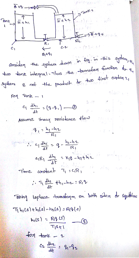
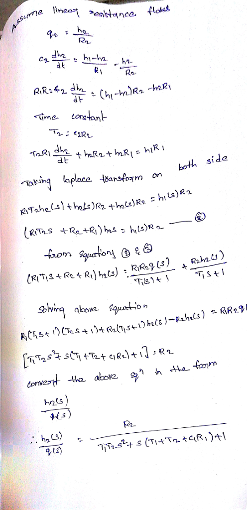
Find G(s)= H2(s)/Q(s)
1.- - For the system shown in the figure, ?+q> Tanque 2 Tanque...
Consider the liquid level system shown in Figure 1. At steady state, the inflow rate and...
 Consider the liquid level system shown in Figure 1. At steady state, the inflow rate and outflow rate are both Ở and the flow rate between the tanks is zero. The heads at tank 1 and tank 2 are both H. At t = 0, the inflow rate is changed from 0 to + , where is the small change in the inflow rate. The resulting changes in the heads (h/ and h2) and flow rates are assumed to be...
Q1. Determine the solution of x(t). 4x + 20% +36x = 0 Where x(0) = 2...
 Q1. Determine the solution of x(t). 4x + 20% +36x = 0 Where x(0) = 2 m, 8(0) = 1 m/s Q1. Mass M is lifted by a pulley system as shown in Figure 1. The pulley is rotating in a clockwise direction. Assuming zero initial conditions, obtain transfer function of the system, X(s)/Ta(s). Τα S B X м k Figure 1 Consider the liquid level system shown in Figure 1. At steady state, the inflow rate and outflow rate...
โ], h Tank 1 4 2 h2 Tank 2 A material balance on this system provides...
 โ], h Tank 1 4 2 h2 Tank 2 A material balance on this system provides the coupled system of ordinary differential equations: dhi Ac at 9-91 dh2 Ac dt = 91-92 Let's assume that the tanks have a maximum height of 1 m and are initially empty, so: h20) = (0) = 0 If the flow exiting the tanks is through valves, then the rate is proportional to the square root of the height of water in the tank:...
5. (10 points) Consider the liquid-level system shown. At steady state, the inflow rate is Q:...
 5. (10 points) Consider the liquid-level system shown. At steady state, the inflow rate is Q: the outflow rates are Q1 and Q, respectively; the flow rate from tank 1 to tank 2 is Q12, and the heads of tanks 1 and 2 are H and H2, respectively. If the inflow rate is changed from Q to Q+q, determine the transfer function Hz(8)/Q(s). Assume the deviations 4,91,92,912, h, and hy are all small. 6th Jan Hathe +7 т/ н+А, JE>,+8....
liquid-level
 Liquid Level System Consider the liquid level system shown below. At steady state, the inflow rate is Q and the outflow rate is also Q Assume that at t = 0 the inflow rate is changed from Q to Q + qr where q, is a small quantity. The disturbance input is qd, which is also a small quantity. Draw a block diagram of the system and simplify it to obtain H 2(s) as a function of Q(s) and Q...
(30pts) Consider the liquid level system shown in the figure. Assume the outflow rate Q (m3/s) th...
 (30pts) Consider the liquid level system shown in the figure. Assume the outflow rate Q (m3/s) through the outflow value is related to the liquid level H by Assume also that, when the inflow rate Qi and outflow rate QOare at Q = 0015m3/s, the liquid level stays at constant H. The capacitance C of the tank is 2m2 Find the steady state value of the liquid level system H. Develop the governing equations for the liquid level system and...
Consider the liquid level control system given in the figure. The values with overbar denote stea...
 Consider the liquid level control system given in the figure. The values with overbar denote steady state values. Draw a block diagram of the system assuming that the changes in the variables are small. Then derive the transfer function between the level of second tank h2 and the disturbance input qd 5. x(t) Lever Valve: q.-Kx Tank 1 O+q oa Tank 2
Consider the liquid level control system given in the figure. The values with overbar denote steady state values....
Consider the liquid level control system given in the figure. The values with overbar denote steady state values. Draw a block diagram of the system assuming that the changes in the variables are small. Then derive the transfer function between the level of second tank h2 and the disturbance input qd 5. x(t) Lever Valve: q.-Kx Tank 1 O+q oa Tank 2
Consider the liquid level control system given in the figure. The values with overbar denote steady state values....
6. Consider the liquid-level system shown. Assume that the outflow rate Q(m/s) through the outflow valve...
 6. Consider the liquid-level system shown. Assume that the outflow rate Q(m/s) through the outflow valve is related to the head H by: Q=kVH = 0.01VH Also assume when the inflow rate Qi is 0.015m3/s the head is constant. At t=0 the inflow valve is closed, so there is no flow for t0. Find the time necessary to empty the tank to half the original head. The area of the tank is 2m2 TIL Capacitance c
3. (40pts) | In the thermal system shown in Figure 7-28(a), it is assumed that the tank is insula...
 3. (40pts) | In the thermal system shown in Figure 7-28(a), it is assumed that the tank is insulated to eliminate heat loss to the surrounding air, that there is no heat storage in the insula tion, and that the liquid in the tank is perfectly mixed so that it is at a uniform temper ature. (Thus, a single temperature can be used to denote both the temperature of the liquid in the tank and that of the outflowing liquid.)...
(20%) Problem 2 The circular tank shown in Figure 2 below has a steady state level of 50 m for a flow rate Q 2.5 m3/s....
 (20%) Problem 2 The circular tank shown in Figure 2 below has a steady state level of 50 m for a flow rate Q 2.5 m3/s. Determine the flow resistance at the outlet If the flow rate is suddenly increased to 2.52 m3/s, Determine: A. (2.5%) B. (7.5%) (5%) (5%) The level of the liquid when the system reaches steady state again. The time constant and the time dependent response of tthe system. The 2% settling time of the system....
 Consider the liquid level system shown in Figure 1. At steady state, the inflow rate and outflow rate are both Ở and the flow rate between the tanks is zero. The heads at tank 1 and tank 2 are both H. At t = 0, the inflow rate is changed from 0 to + , where is the small change in the inflow rate. The resulting changes in the heads (h/ and h2) and flow rates are assumed to be...
 Q1. Determine the solution of x(t). 4x + 20% +36x = 0 Where x(0) = 2 m, 8(0) = 1 m/s Q1. Mass M is lifted by a pulley system as shown in Figure 1. The pulley is rotating in a clockwise direction. Assuming zero initial conditions, obtain transfer function of the system, X(s)/Ta(s). Τα S B X м k Figure 1 Consider the liquid level system shown in Figure 1. At steady state, the inflow rate and outflow rate...
 โ], h Tank 1 4 2 h2 Tank 2 A material balance on this system provides the coupled system of ordinary differential equations: dhi Ac at 9-91 dh2 Ac dt = 91-92 Let's assume that the tanks have a maximum height of 1 m and are initially empty, so: h20) = (0) = 0 If the flow exiting the tanks is through valves, then the rate is proportional to the square root of the height of water in the tank:...
 5. (10 points) Consider the liquid-level system shown. At steady state, the inflow rate is Q: the outflow rates are Q1 and Q, respectively; the flow rate from tank 1 to tank 2 is Q12, and the heads of tanks 1 and 2 are H and H2, respectively. If the inflow rate is changed from Q to Q+q, determine the transfer function Hz(8)/Q(s). Assume the deviations 4,91,92,912, h, and hy are all small. 6th Jan Hathe +7 т/ н+А, JE>,+8....
 Liquid Level System Consider the liquid level system shown below. At steady state, the inflow rate is Q and the outflow rate is also Q Assume that at t = 0 the inflow rate is changed from Q to Q + qr where q, is a small quantity. The disturbance input is qd, which is also a small quantity. Draw a block diagram of the system and simplify it to obtain H 2(s) as a function of Q(s) and Q...
 (30pts) Consider the liquid level system shown in the figure. Assume the outflow rate Q (m3/s) through the outflow value is related to the liquid level H by Assume also that, when the inflow rate Qi and outflow rate QOare at Q = 0015m3/s, the liquid level stays at constant H. The capacitance C of the tank is 2m2 Find the steady state value of the liquid level system H. Develop the governing equations for the liquid level system and...
 Consider the liquid level control system given in the figure. The values with overbar denote steady state values. Draw a block diagram of the system assuming that the changes in the variables are small. Then derive the transfer function between the level of second tank h2 and the disturbance input qd 5. x(t) Lever Valve: q.-Kx Tank 1 O+q oa Tank 2
Consider the liquid level control system given in the figure. The values with overbar denote steady state values....
Consider the liquid level control system given in the figure. The values with overbar denote steady state values. Draw a block diagram of the system assuming that the changes in the variables are small. Then derive the transfer function between the level of second tank h2 and the disturbance input qd 5. x(t) Lever Valve: q.-Kx Tank 1 O+q oa Tank 2
Consider the liquid level control system given in the figure. The values with overbar denote steady state values....
 6. Consider the liquid-level system shown. Assume that the outflow rate Q(m/s) through the outflow valve is related to the head H by: Q=kVH = 0.01VH Also assume when the inflow rate Qi is 0.015m3/s the head is constant. At t=0 the inflow valve is closed, so there is no flow for t0. Find the time necessary to empty the tank to half the original head. The area of the tank is 2m2 TIL Capacitance c
 3. (40pts) | In the thermal system shown in Figure 7-28(a), it is assumed that the tank is insulated to eliminate heat loss to the surrounding air, that there is no heat storage in the insula tion, and that the liquid in the tank is perfectly mixed so that it is at a uniform temper ature. (Thus, a single temperature can be used to denote both the temperature of the liquid in the tank and that of the outflowing liquid.)...
 (20%) Problem 2 The circular tank shown in Figure 2 below has a steady state level of 50 m for a flow rate Q 2.5 m3/s. Determine the flow resistance at the outlet If the flow rate is suddenly increased to 2.52 m3/s, Determine: A. (2.5%) B. (7.5%) (5%) (5%) The level of the liquid when the system reaches steady state again. The time constant and the time dependent response of tthe system. The 2% settling time of the system....
Most questions answered within 3 hours.
-
Problem 1 (Logistic Regression and KNN). In this problem, we
predict Direction using the data Weekly.csv....
asked 1 minute from now -
Design a class Holiday that represents a
holiday during the year. This class has three
private...
asked 27 seconds ago -
What is the difference between VNTRs (Variable Number Tandem
Repeats) and STRs (Short Tandem Repeats) used...
asked 4 minutes ago -
Fill in
Isotope: 15 O
1. Element name:
2. Atomic number:
3. Mass number:
4. Number...
asked 4 minutes ago -
These days with the cost of a college education it is important
to be able to...
asked 12 minutes ago -
c++
Implement Radix Sort Most sorting algorithms, like bubble,
insertion, selection and shell follow similar implementations....
asked 19 minutes ago -
Many adult tissues contain terminally differentiated cells that
are incapable of proliferation. How can these tissues...
asked 20 minutes ago -
A survey of tobacco use in high schools tested the saliva of
female and male students...
asked 40 minutes ago -
Assume that the mutation rate for a given gene is
510-6 mutations per gene per generation....
asked 39 minutes ago -
The majority of innovation organizational communication has
been driven by technological advancements in the past thirty...
asked 40 minutes ago -
If one motor has three times as much power as another, then the
smaller power motor:...
asked 38 minutes ago -
Discuss at least four issues that are important to
accountants.
I need 2 pages of explanations
asked 39 minutes ago