
Homework Answers
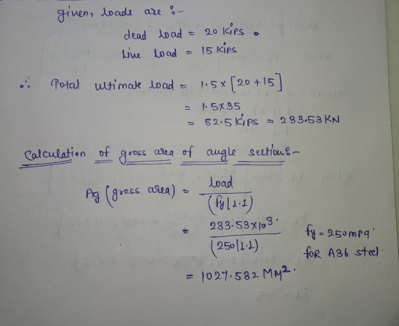


given, loads are s- dead load = 20 kips . live load = 15 kips . Potal ultimate load = 1.5% [20 +15) = 1.5x35 2 52:56ps 233.53 KN Calculation of gross area of angle sections load in Ag (gross area) = fy | 2.1) 233-53X103 (250/1-2) fy = 250 mpa! FOR ABG stel = 1027.582 MM².
Select angle section 4² x 4² x 1 having roles sectional area - 1.94 inch 1251.61 mm2 " assuning bolt used is of 20 mm dia with 22mm bolt hall dia and grade of 4.6 . feb a 400 i shear strength of bult areax hub 1.2553 -0.18x x0x 402553 - 45.272 KN & Bearing strength of bett = 2.5 kod dmin fup 1-25 where Kounin do -0.25, the ] assome e = 1.5 do send/edge distance P (pitch) & 2.5d felb= 4oo. fup - 410 400 / Where Rb-N f. 5 do 3 do 2.5d 3 do 25, U10 4102 where Ko - Min the sales 25d -0.25, vero, 2] Kos. Min 0.5, 29620 -0.25, 09,4] 16 - Miu (0.5, 2150 -5015, 0-9, 1] Kb = 0.5
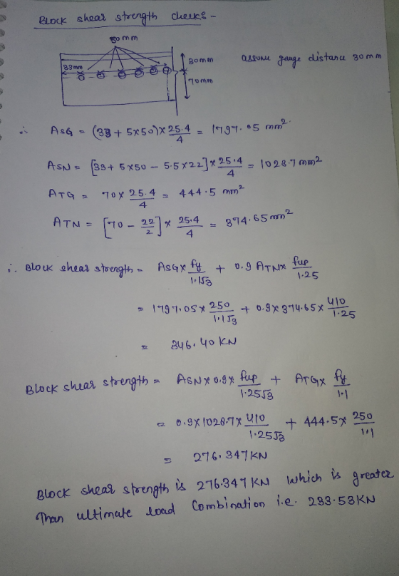
Block checks - shear strength 50 mm 20 gom assone gauge distance 30mm 83 10mm 4 AsQ - (38+5x500x 25.4 . 1194.65 mm? Asn = (33+ 5 x50 - 5-5 X22]* 2514 - 10287 m2 ATG - 90x 25.4 - 444.5 mm? ATN = 170 - 227* 254 - 374.65 mm? i. Block shear strength - AsGxfy + 0.9 Aux fupes 1-25 ulo 1191.08 250 + 0,9x374.65% 7. 1.25 TIS 846.40 KN Block shear strength ASNxogx fup + ArGx Py 1.2553 0.941020.7x U10 + 444.5x 250 1.2533 276.347 KN Block shear strength is 276.347 KN which is greater Than ultimate load Combination le 233.53KN
2 1.25 e. Bearing stoungth of balt 2.5x0.5x20x 25.4x U10 Los here it is assumed that gusset e plate thickeness is more than angle sution anickeness. & Bearing strength of bolt = 208.28 KN = 52.07 KN o strength of bott min of (shear strength, Bearing stength) = 45.272 KN a. No. of belts Required a 238.53 5.158 45.212 - 6 boults Tue 6 belts . fuse 6 balts Net area strength of augle section or Net area = (4 +4° -4 -0.866') * = 1.721 inch? = 110.3204 mm2 Net area strength of angle = 0.g Anet & fups - 0.9x10.32048 Motos = 327.76 KN There fore in Met area strength angle is safe.
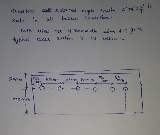
There fare safe in sold selected all failure 4² angle section Conditions. Balts typical used cross are of Romm dia blith 4.6 section is as below! grade. 30mm 33m 50mm 50mm, 50mm 5 mm Tomm
Add Answer to:
3. Design a tension member using a single angle of A36 steel with bolted connections (4...
Steel Design 2. (50 pts) Design an A36-steel tension member 16 ft long consisting of two...
 Steel Design
2. (50 pts) Design an A36-steel tension member 16 ft long consisting of two channels, bolted through their webs to a single 1 inch gusset plate, to transmit 75 kips DL and 93 kips LL. The bolts are 7/8 in. Bolt spacing 4 inch and bolt edge distance 3 inch. In addition to checking block shear in the channels, design the thickness of the gusset plate to resist block shear.
Steel Design
2. (50 pts) Design an A36-steel tension member 16 ft long consisting of two channels, bolted through their webs to a single 1 inch gusset plate, to transmit 75 kips DL and 93 kips LL. The bolts are 7/8 in. Bolt spacing 4 inch and bolt edge distance 3 inch. In addition to checking block shear in the channels, design the thickness of the gusset plate to resist block shear.
4) Find the most efficient (i.e., with the smallest weight per unit length) single angle tension...
 4) Find the most efficient (i.e., with the smallest weight per unit length) single angle tension member of A36 steel to resist the following service loads: dead load- 60 kips, live load 120 kips, and wind load = 50 kips. The member will be connected through one leg with 3/4-in diameter bolts in two lines and four or more bolts in each line (see figure below). Assume that the bolts are aligned and shear block failure is prevented. The member...
Design the lightest available W14 (A992) tension member by the 2016 AISC LRFD for a truss...
 Design the lightest available W14 (A992) tension member by the 2016 AISC LRFD for a truss that will carry service DL = 100 kips and service LL = 320 kips. The member is 30 ft. long. The flanges will be bolted to the connection plates (A36) with -in bolts so that four bolts will appear on the cross-section Assume there are at least three bolts per line, standard holes, and the connection is adequate. Hint: Consider all applicable limit states.
S- Section FIGURE P3.2-3 APL⅜x6tension member is steel is A36. Assume that A, A, and compute...
 S- Section FIGURE P3.2-3 APL⅜x6tension member is steel is A36. Assume that A, A, and compute the following. a. The design strength for LRFD. b. The allowable strength for ASD. 32-4 APLx6 tension member is welded to a gusset plate as shown in Figure P3.2-4. The :and compute 3.2-4 ameter bolts, as shown A,A, and compute the FIGURE P3.2-4 ion member shown in Figure P3.2.5 is a PL tax 8 of A36 steel. The mem- ted to a gusset plate...
which has l A single angle tension member,Ladx3/8 kength of 7 and o'% as show bl, is made from A36 steel is connect to 3/8-in thickness ckness gust plate are 28 kips dead load and 20 kips usi...
 which has l A single angle tension member,Ladx3/8 kength of 7 and o'% as show bl, is made from A36 steel is connect to 3/8-in thickness ckness gust plate are 28 kips dead load and 20 kips using LRFD method and AISC )." The wrvice loads are 28 kips The servive By live load yewifivations determine the followings ) The adeyuacy of this member 2) Check Ar slenderness /s" PL
which has l A single angle tension member,Ladx3/8 kength of...
which has l A single angle tension member,Ladx3/8 kength of 7 and o'% as show bl, is made from A36 steel is connect to 3/8-in thickness ckness gust plate are 28 kips dead load and 20 kips using LRFD method and AISC )." The wrvice loads are 28 kips The servive By live load yewifivations determine the followings ) The adeyuacy of this member 2) Check Ar slenderness /s" PL
which has l A single angle tension member,Ladx3/8 kength of...
Pleqse show details and formulas. Select a single-angle tension member of A36 steel to resist a dead load of 20 kips and a live load of 50 kips. The length of the member is 20 feet, and it will...
 Pleqse show details and formulas.
Select a single-angle tension member of A36 steel to resist a dead load of 20 kips and a live load of 50 kips. The length of the member is 20 feet, and it will be connected to a %-inch thick gusset plate with one line of 3/4-inch- diameter bolts through the long legs. There will be four or more bolts in this Q1) line
Select a single-angle tension member of A36 steel to resist a...
Pleqse show details and formulas.
Select a single-angle tension member of A36 steel to resist a dead load of 20 kips and a live load of 50 kips. The length of the member is 20 feet, and it will be connected to a %-inch thick gusset plate with one line of 3/4-inch- diameter bolts through the long legs. There will be four or more bolts in this Q1) line
Select a single-angle tension member of A36 steel to resist a...
Design a slip-critical bolted connection for the following conditions: • All structural steel is A36 •...
 Design a slip-critical bolted connection for the following conditions: • All structural steel is A36 • Length = 10 ft. • The tension member is 2L7 x 4 x 7/16 LLBB. • The connection will be to a 3/8-inch-thick gusset plate • Service dead load = 50 kips and service live load = 100 kips. Provide a complete sketch showing all information needed for the fabrication of the connection. Use LRFD.
Design a tension member and its connection for the following conditions: . Length 15 feet ....
 Design a tension member and its connection for the following conditions: . Length 15 feet . The connection will be to a Vs-inch-thick gusset plate 3 All structural steel is A36 The connection will be bolted. Slip is not permitted . Service dead load 45 kips and service live load 105 kips Select a double-angle section with unequal legs, long legs back-to-back. Provide a complete sketch showing all information needed for the fab- rication of the connection. a. Use LRFD
3. A C 9x15 is to be used as a tension member. The channel is bolted to a 5/8 in gusset plate wit...
 3. A C 9x15 is to be used as a tension member. The channel is bolted to a 5/8 in gusset plate with 7/8 inch diameter, A307 bolts. The tension member is AS72 Grade 50 steel and the gusset plate is A36. Follow Figure 3. (a) Check all spacing and edge distance irements; (b) Compute the design strength based on shear and bearing; and (c) Compute the allowable strength based on shear and bearing. 23" 3" 3" С 9x 15...
please help solve these problems Section 19.4 High-Strength Bolted Connections 19.1 Compute the allowable tensile load for the single-shear lap joint shown. The plates are ASTM A36 steel and t...
 please help solve these problems
Section 19.4 High-Strength Bolted Connections 19.1 Compute the allowable tensile load for the single-shear lap joint shown. The plates are ASTM A36 steel and the high-strength bolts are g-in.-diameter A325 bolts in stan- dard holes. Assume a bearing-type connection with threads excluded from the shear plane (A325-X) 19.2 Rework Problem 19.1 assuming a bearing-type connection with bolt threads in the shear plane (A325-N).
Section 19.4 High-Strength Bolted Connections 19.1 Compute the allowable tensile load for...
please help solve these problems
Section 19.4 High-Strength Bolted Connections 19.1 Compute the allowable tensile load for the single-shear lap joint shown. The plates are ASTM A36 steel and the high-strength bolts are g-in.-diameter A325 bolts in stan- dard holes. Assume a bearing-type connection with threads excluded from the shear plane (A325-X) 19.2 Rework Problem 19.1 assuming a bearing-type connection with bolt threads in the shear plane (A325-N).
Section 19.4 High-Strength Bolted Connections 19.1 Compute the allowable tensile load for...
 Steel Design
2. (50 pts) Design an A36-steel tension member 16 ft long consisting of two channels, bolted through their webs to a single 1 inch gusset plate, to transmit 75 kips DL and 93 kips LL. The bolts are 7/8 in. Bolt spacing 4 inch and bolt edge distance 3 inch. In addition to checking block shear in the channels, design the thickness of the gusset plate to resist block shear.
Steel Design
2. (50 pts) Design an A36-steel tension member 16 ft long consisting of two channels, bolted through their webs to a single 1 inch gusset plate, to transmit 75 kips DL and 93 kips LL. The bolts are 7/8 in. Bolt spacing 4 inch and bolt edge distance 3 inch. In addition to checking block shear in the channels, design the thickness of the gusset plate to resist block shear.
 4) Find the most efficient (i.e., with the smallest weight per unit length) single angle tension member of A36 steel to resist the following service loads: dead load- 60 kips, live load 120 kips, and wind load = 50 kips. The member will be connected through one leg with 3/4-in diameter bolts in two lines and four or more bolts in each line (see figure below). Assume that the bolts are aligned and shear block failure is prevented. The member...
 Design the lightest available W14 (A992) tension member by the 2016 AISC LRFD for a truss that will carry service DL = 100 kips and service LL = 320 kips. The member is 30 ft. long. The flanges will be bolted to the connection plates (A36) with -in bolts so that four bolts will appear on the cross-section Assume there are at least three bolts per line, standard holes, and the connection is adequate. Hint: Consider all applicable limit states.
 S- Section FIGURE P3.2-3 APL⅜x6tension member is steel is A36. Assume that A, A, and compute the following. a. The design strength for LRFD. b. The allowable strength for ASD. 32-4 APLx6 tension member is welded to a gusset plate as shown in Figure P3.2-4. The :and compute 3.2-4 ameter bolts, as shown A,A, and compute the FIGURE P3.2-4 ion member shown in Figure P3.2.5 is a PL tax 8 of A36 steel. The mem- ted to a gusset plate...
 which has l A single angle tension member,Ladx3/8 kength of 7 and o'% as show bl, is made from A36 steel is connect to 3/8-in thickness ckness gust plate are 28 kips dead load and 20 kips using LRFD method and AISC )." The wrvice loads are 28 kips The servive By live load yewifivations determine the followings ) The adeyuacy of this member 2) Check Ar slenderness /s" PL
which has l A single angle tension member,Ladx3/8 kength of...
which has l A single angle tension member,Ladx3/8 kength of 7 and o'% as show bl, is made from A36 steel is connect to 3/8-in thickness ckness gust plate are 28 kips dead load and 20 kips using LRFD method and AISC )." The wrvice loads are 28 kips The servive By live load yewifivations determine the followings ) The adeyuacy of this member 2) Check Ar slenderness /s" PL
which has l A single angle tension member,Ladx3/8 kength of...
 Pleqse show details and formulas.
Select a single-angle tension member of A36 steel to resist a dead load of 20 kips and a live load of 50 kips. The length of the member is 20 feet, and it will be connected to a %-inch thick gusset plate with one line of 3/4-inch- diameter bolts through the long legs. There will be four or more bolts in this Q1) line
Select a single-angle tension member of A36 steel to resist a...
Pleqse show details and formulas.
Select a single-angle tension member of A36 steel to resist a dead load of 20 kips and a live load of 50 kips. The length of the member is 20 feet, and it will be connected to a %-inch thick gusset plate with one line of 3/4-inch- diameter bolts through the long legs. There will be four or more bolts in this Q1) line
Select a single-angle tension member of A36 steel to resist a...
 Design a slip-critical bolted connection for the following conditions: • All structural steel is A36 • Length = 10 ft. • The tension member is 2L7 x 4 x 7/16 LLBB. • The connection will be to a 3/8-inch-thick gusset plate • Service dead load = 50 kips and service live load = 100 kips. Provide a complete sketch showing all information needed for the fabrication of the connection. Use LRFD.
 Design a tension member and its connection for the following conditions: . Length 15 feet . The connection will be to a Vs-inch-thick gusset plate 3 All structural steel is A36 The connection will be bolted. Slip is not permitted . Service dead load 45 kips and service live load 105 kips Select a double-angle section with unequal legs, long legs back-to-back. Provide a complete sketch showing all information needed for the fab- rication of the connection. a. Use LRFD
 3. A C 9x15 is to be used as a tension member. The channel is bolted to a 5/8 in gusset plate with 7/8 inch diameter, A307 bolts. The tension member is AS72 Grade 50 steel and the gusset plate is A36. Follow Figure 3. (a) Check all spacing and edge distance irements; (b) Compute the design strength based on shear and bearing; and (c) Compute the allowable strength based on shear and bearing. 23" 3" 3" С 9x 15...
 please help solve these problems
Section 19.4 High-Strength Bolted Connections 19.1 Compute the allowable tensile load for the single-shear lap joint shown. The plates are ASTM A36 steel and the high-strength bolts are g-in.-diameter A325 bolts in stan- dard holes. Assume a bearing-type connection with threads excluded from the shear plane (A325-X) 19.2 Rework Problem 19.1 assuming a bearing-type connection with bolt threads in the shear plane (A325-N).
Section 19.4 High-Strength Bolted Connections 19.1 Compute the allowable tensile load for...
please help solve these problems
Section 19.4 High-Strength Bolted Connections 19.1 Compute the allowable tensile load for the single-shear lap joint shown. The plates are ASTM A36 steel and the high-strength bolts are g-in.-diameter A325 bolts in stan- dard holes. Assume a bearing-type connection with threads excluded from the shear plane (A325-X) 19.2 Rework Problem 19.1 assuming a bearing-type connection with bolt threads in the shear plane (A325-N).
Section 19.4 High-Strength Bolted Connections 19.1 Compute the allowable tensile load for...
Most questions answered within 3 hours.
-
Madtack Company uses a job-order costing system and started the month
of March with only one...
asked 15 seconds ago -
Describe how to distinguish true motility from brownian motion
and fluid flow when viewing a wet...
asked 3 minutes ago -
A manufacturer of game controllers is concerned that its
controller may be difficult for left-handed users....
asked 5 minutes ago -
Water at gauge pressure of 3.8 atmospheres at street level
enters an office building at 0.60...
asked 19 minutes ago -
Quick question, I want to know how to convert decimal numbers to
binary number, when i...
asked 40 minutes ago -
You found out that now you are going to receive payments of
$8,500 for the next...
asked 44 minutes ago -
17.
Technician A says that leaking components are usually repaired
rather than replaced. Technician B says...
asked 44 minutes ago -
A) An Operon is:?
1- A gene that affect another gene
transcription.
2. A gene coding...
asked 51 minutes ago -
When opening a file, use this method to determine whether a file
exists before you attempt...
asked 56 minutes ago -
Sales total $300,000 when variable costs total $180,000 and
fixed costs are $60,000. Breakeven sales total:...
asked 1 hour ago -
1)
To calculate the depth of a water well, an explorer drops a stone and with...
asked 1 hour ago -
0.429-g sample of gas occupies 125 mL at 60. cm of Hg and 25°C.
The molar...
asked 1 hour ago