
Homework Answers

Add Answer to:
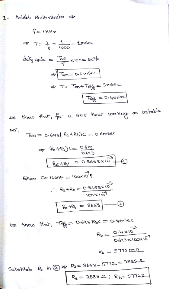
1. Consider the astable multivibrator circuit given in Fig. 4.6 with C 100 nF and Vcc-5...
2. Now consider the monostable circuit of Fig. 4.7. Assume RA 100 k2. Reset Discharge Threshold...
 2. Now consider the monostable circuit of Fig. 4.7. Assume RA 100 k2. Reset Discharge Threshold 555 Output Trigger Ground vo Vin U) Fig. 4.7.Monostable Multivibrator 555 IC Determine C to get a monopulse of approximately 5 sec.
Can you Solve this question? III) (10/50) Given the following circuit 1) What is the nature of this circuit 2) Explain...
 Can you Solve this question?
III) (10/50) Given the following circuit 1) What is the nature of this circuit 2) Explain the principle of operation of this 555 multivibrator circuit 3) Draw the waveform of the output voltage Vo and V at pin 2 4) Find the expression of the pulse width W of the output voltage in terms of RA and C. 5) Given RA-1 00kΩand C 10μF. Calculate w 6) What are the differences between this circuit and...
Can you Solve this question?
III) (10/50) Given the following circuit 1) What is the nature of this circuit 2) Explain the principle of operation of this 555 multivibrator circuit 3) Draw the waveform of the output voltage Vo and V at pin 2 4) Find the expression of the pulse width W of the output voltage in terms of RA and C. 5) Given RA-1 00kΩand C 10μF. Calculate w 6) What are the differences between this circuit and...
A basic change to the astable circuit allows the 555 timer to be used as a triangle waveform generator. What is the func...
 A basic change to the astable circuit allows the 555 timer to be
used as a triangle waveform generator. What is the
function of the “RC circuit” part? Briefly explain
why we can obtain triangle waveform in the circuit. Hint:
“integrator”.
+VCC X1 VCC Rint gk R1 9k 2 TRIGGER RESET OUTPUT CONTROL THRESHOLD C5 DISCHARGE 0.1u D1 R2 10k GND D1N4002 1555D C3 C2 0.01u 0.01u integrator part
+VCC X1 VCC Rint gk R1 9k 2 TRIGGER RESET OUTPUT...
A basic change to the astable circuit allows the 555 timer to be
used as a triangle waveform generator. What is the
function of the “RC circuit” part? Briefly explain
why we can obtain triangle waveform in the circuit. Hint:
“integrator”.
+VCC X1 VCC Rint gk R1 9k 2 TRIGGER RESET OUTPUT CONTROL THRESHOLD C5 DISCHARGE 0.1u D1 R2 10k GND D1N4002 1555D C3 C2 0.01u 0.01u integrator part
+VCC X1 VCC Rint gk R1 9k 2 TRIGGER RESET OUTPUT...
Can you Solve this question? III) (10/50) Given the following circuit 1) What is the nature...
 Can you Solve this question?
III) (10/50) Given the following circuit 1) What is the nature of this circuit 2) Explain the principle of operation of this 555 multivibrator circuit 3) Draw the waveform of the output voltage Vo and V at pin 2 4) Find the expression of the pulse width W of the output voltage in terms of RA and C. 5) Given RA-1 00kΩand C 10μF. Calculate w 6) What are the differences between this circuit and...
Can you Solve this question?
III) (10/50) Given the following circuit 1) What is the nature of this circuit 2) Explain the principle of operation of this 555 multivibrator circuit 3) Draw the waveform of the output voltage Vo and V at pin 2 4) Find the expression of the pulse width W of the output voltage in terms of RA and C. 5) Given RA-1 00kΩand C 10μF. Calculate w 6) What are the differences between this circuit and...
Question 8 (6 marks) You have been given a 555 Timer, an LED with Von-2V, a 9V battery that can comfortably supply 5mA...
 Question 8 (6 marks) You have been given a 555 Timer, an LED with Von-2V, a 9V battery that can comfortably supply 5mA of current without loss of voltage, a 1uF capacitor and access to any resistor values you want. Design a circuit that causes the LED to flash periodically once per second with a duty cycle of 75% Ensure that it does not draw more than 5mA of current from the battery (i.e 3mA of charging current and 2mA...
Problem 5 1. Design a monostable multivibrator using the 555 imer IC Fip Dop 100 ?...
 Problem 5 1. Design a monostable multivibrator using the 555 imer IC Fip Dop 100 ? multivibrator, find the period over which the output signal remains high if the negative trigger impulse remains low for 3ms. 2. If a lkS2 resistor and a 5?F capacitor are used to design the above Pag
(a) Design a inverting Schmitt trigger circuit to be used as a zero crossing detector with transition voltages about ±25...
 (a) Design a inverting Schmitt trigger circuit
to be used as a zero crossing detector with transition voltages
about ±25 mV. Assume the saturation voltages for the op–amp are ±13
V. Draw the voltage transfer characteristic (VTC), i.e., vout vs.
vin.
(b) Design an astable multivibrator to produce
a square signal with a frequency of 1 kHz using C=0.01 µF, R1 = 30
kΩ, and R2 = 20 kΩ. Sketch the circuit waveforms (vo, v +, and v −)
assuming...
(a) Design a inverting Schmitt trigger circuit
to be used as a zero crossing detector with transition voltages
about ±25 mV. Assume the saturation voltages for the op–amp are ±13
V. Draw the voltage transfer characteristic (VTC), i.e., vout vs.
vin.
(b) Design an astable multivibrator to produce
a square signal with a frequency of 1 kHz using C=0.01 µF, R1 = 30
kΩ, and R2 = 20 kΩ. Sketch the circuit waveforms (vo, v +, and v −)
assuming...
ans, RA = 721.5 kohms, RB = 360.8 kohms, R3 = 3.5kohms as an example solution. Question 7 (6 marks) You have been given...
 ans,
RA = 721.5 kohms, RB = 360.8 kohms, R3 = 3.5kohms as an example
solution.
Question 7 (6 marks) You have been given a 555 Timer, an LED with Von 2V, a 9V battery that can comfortably supply 5mA of current without loss of voltage, a 1 μF capacitor and access to any resistor values you want. You are to design a circuit that causes the LED to flash periodically once per second with a duty cycle of 75%....
ans,
RA = 721.5 kohms, RB = 360.8 kohms, R3 = 3.5kohms as an example
solution.
Question 7 (6 marks) You have been given a 555 Timer, an LED with Von 2V, a 9V battery that can comfortably supply 5mA of current without loss of voltage, a 1 μF capacitor and access to any resistor values you want. You are to design a circuit that causes the LED to flash periodically once per second with a duty cycle of 75%....
Circuit Analysis Vcc +Vcc 10 k2 R3 1kn 4 1 k2 Voi 7 555 A oVo...
 Circuit Analysis
Vcc +Vcc 10 k2 R3 1kn 4 1 k2 Voi 7 555 A oVo 3 555 2 R4 10 kn R2 2 1 MQ 5 5 6 C1 1 F C3 0.1 uF C4 10 nF C2 10 nF I Figure Q2 4 Figure Q2 shows an oscillator circuit using two 555 timers. Assume that the reset pin is active low. When the switch is opened: (i) Draw the output waveform (V01) of Timer A indicating clearly the...
Circuit Analysis
Vcc +Vcc 10 k2 R3 1kn 4 1 k2 Voi 7 555 A oVo 3 555 2 R4 10 kn R2 2 1 MQ 5 5 6 C1 1 F C3 0.1 uF C4 10 nF C2 10 nF I Figure Q2 4 Figure Q2 shows an oscillator circuit using two 555 timers. Assume that the reset pin is active low. When the switch is opened: (i) Draw the output waveform (V01) of Timer A indicating clearly the...
Data Converters and Timing Circuits (20 marks) (a) For the timing circuit shown below, use a 1000pF capacitor and find the values of RA and RB that result in an oscillation frequency of 100KHz an...
 Data Converters and Timing Circuits (20 marks) (a) For the timing circuit shown below, use a 1000pF capacitor and find the values of RA and RB that result in an oscillation frequency of 100KHz and a duty cycle of 75% Reset 0.693 R,+2R,)C Discharge Outpat Threshold Trigger Ground Duty-Cle2R R,+2R, ar (b) The 4-Bit Weighted-Resistor DAC Converter shown below is to be expanded into an 8-bit device a. What are the required values of the additional resistors to be added?...
 2. Now consider the monostable circuit of Fig. 4.7. Assume RA 100 k2. Reset Discharge Threshold 555 Output Trigger Ground vo Vin U) Fig. 4.7.Monostable Multivibrator 555 IC Determine C to get a monopulse of approximately 5 sec.
 Can you Solve this question?
III) (10/50) Given the following circuit 1) What is the nature of this circuit 2) Explain the principle of operation of this 555 multivibrator circuit 3) Draw the waveform of the output voltage Vo and V at pin 2 4) Find the expression of the pulse width W of the output voltage in terms of RA and C. 5) Given RA-1 00kΩand C 10μF. Calculate w 6) What are the differences between this circuit and...
Can you Solve this question?
III) (10/50) Given the following circuit 1) What is the nature of this circuit 2) Explain the principle of operation of this 555 multivibrator circuit 3) Draw the waveform of the output voltage Vo and V at pin 2 4) Find the expression of the pulse width W of the output voltage in terms of RA and C. 5) Given RA-1 00kΩand C 10μF. Calculate w 6) What are the differences between this circuit and...
 A basic change to the astable circuit allows the 555 timer to be
used as a triangle waveform generator. What is the
function of the “RC circuit” part? Briefly explain
why we can obtain triangle waveform in the circuit. Hint:
“integrator”.
+VCC X1 VCC Rint gk R1 9k 2 TRIGGER RESET OUTPUT CONTROL THRESHOLD C5 DISCHARGE 0.1u D1 R2 10k GND D1N4002 1555D C3 C2 0.01u 0.01u integrator part
+VCC X1 VCC Rint gk R1 9k 2 TRIGGER RESET OUTPUT...
A basic change to the astable circuit allows the 555 timer to be
used as a triangle waveform generator. What is the
function of the “RC circuit” part? Briefly explain
why we can obtain triangle waveform in the circuit. Hint:
“integrator”.
+VCC X1 VCC Rint gk R1 9k 2 TRIGGER RESET OUTPUT CONTROL THRESHOLD C5 DISCHARGE 0.1u D1 R2 10k GND D1N4002 1555D C3 C2 0.01u 0.01u integrator part
+VCC X1 VCC Rint gk R1 9k 2 TRIGGER RESET OUTPUT...
 Can you Solve this question?
III) (10/50) Given the following circuit 1) What is the nature of this circuit 2) Explain the principle of operation of this 555 multivibrator circuit 3) Draw the waveform of the output voltage Vo and V at pin 2 4) Find the expression of the pulse width W of the output voltage in terms of RA and C. 5) Given RA-1 00kΩand C 10μF. Calculate w 6) What are the differences between this circuit and...
Can you Solve this question?
III) (10/50) Given the following circuit 1) What is the nature of this circuit 2) Explain the principle of operation of this 555 multivibrator circuit 3) Draw the waveform of the output voltage Vo and V at pin 2 4) Find the expression of the pulse width W of the output voltage in terms of RA and C. 5) Given RA-1 00kΩand C 10μF. Calculate w 6) What are the differences between this circuit and...
 Question 8 (6 marks) You have been given a 555 Timer, an LED with Von-2V, a 9V battery that can comfortably supply 5mA of current without loss of voltage, a 1uF capacitor and access to any resistor values you want. Design a circuit that causes the LED to flash periodically once per second with a duty cycle of 75% Ensure that it does not draw more than 5mA of current from the battery (i.e 3mA of charging current and 2mA...
 Problem 5 1. Design a monostable multivibrator using the 555 imer IC Fip Dop 100 ? multivibrator, find the period over which the output signal remains high if the negative trigger impulse remains low for 3ms. 2. If a lkS2 resistor and a 5?F capacitor are used to design the above Pag
 (a) Design a inverting Schmitt trigger circuit
to be used as a zero crossing detector with transition voltages
about ±25 mV. Assume the saturation voltages for the op–amp are ±13
V. Draw the voltage transfer characteristic (VTC), i.e., vout vs.
vin.
(b) Design an astable multivibrator to produce
a square signal with a frequency of 1 kHz using C=0.01 µF, R1 = 30
kΩ, and R2 = 20 kΩ. Sketch the circuit waveforms (vo, v +, and v −)
assuming...
(a) Design a inverting Schmitt trigger circuit
to be used as a zero crossing detector with transition voltages
about ±25 mV. Assume the saturation voltages for the op–amp are ±13
V. Draw the voltage transfer characteristic (VTC), i.e., vout vs.
vin.
(b) Design an astable multivibrator to produce
a square signal with a frequency of 1 kHz using C=0.01 µF, R1 = 30
kΩ, and R2 = 20 kΩ. Sketch the circuit waveforms (vo, v +, and v −)
assuming...
 ans,
RA = 721.5 kohms, RB = 360.8 kohms, R3 = 3.5kohms as an example
solution.
Question 7 (6 marks) You have been given a 555 Timer, an LED with Von 2V, a 9V battery that can comfortably supply 5mA of current without loss of voltage, a 1 μF capacitor and access to any resistor values you want. You are to design a circuit that causes the LED to flash periodically once per second with a duty cycle of 75%....
ans,
RA = 721.5 kohms, RB = 360.8 kohms, R3 = 3.5kohms as an example
solution.
Question 7 (6 marks) You have been given a 555 Timer, an LED with Von 2V, a 9V battery that can comfortably supply 5mA of current without loss of voltage, a 1 μF capacitor and access to any resistor values you want. You are to design a circuit that causes the LED to flash periodically once per second with a duty cycle of 75%....
 Circuit Analysis
Vcc +Vcc 10 k2 R3 1kn 4 1 k2 Voi 7 555 A oVo 3 555 2 R4 10 kn R2 2 1 MQ 5 5 6 C1 1 F C3 0.1 uF C4 10 nF C2 10 nF I Figure Q2 4 Figure Q2 shows an oscillator circuit using two 555 timers. Assume that the reset pin is active low. When the switch is opened: (i) Draw the output waveform (V01) of Timer A indicating clearly the...
Circuit Analysis
Vcc +Vcc 10 k2 R3 1kn 4 1 k2 Voi 7 555 A oVo 3 555 2 R4 10 kn R2 2 1 MQ 5 5 6 C1 1 F C3 0.1 uF C4 10 nF C2 10 nF I Figure Q2 4 Figure Q2 shows an oscillator circuit using two 555 timers. Assume that the reset pin is active low. When the switch is opened: (i) Draw the output waveform (V01) of Timer A indicating clearly the...
 Data Converters and Timing Circuits (20 marks) (a) For the timing circuit shown below, use a 1000pF capacitor and find the values of RA and RB that result in an oscillation frequency of 100KHz and a duty cycle of 75% Reset 0.693 R,+2R,)C Discharge Outpat Threshold Trigger Ground Duty-Cle2R R,+2R, ar (b) The 4-Bit Weighted-Resistor DAC Converter shown below is to be expanded into an 8-bit device a. What are the required values of the additional resistors to be added?...
Most questions answered within 3 hours.
-
A solid, uniform disk of radius 0.250 m and mass 53.7 kg rolls
down a ramp...
asked 1 hour ago -
Given the following table of high speed internet access vs.
annual home income:
Home Income
%...
asked 1 hour ago -
A baseball batter hits a 0.145kg baseball straight up into the
air. The baseball leaves the...
asked 2 hours ago -
An FM modulator is tested using
single-tone baseband signal with frequency of 50kHz and a sprectrum...
asked 2 hours ago -
Write the ionic equations for the first stage of salts
hydrolysis.
Anion, Cation?
Na2S
NiSO4
K2SO4...
asked 4 hours ago -
suppose there is a normally distributed population with a mean of
250 and a standard deviation...
asked 4 hours ago -
Question Three
Suppose you as project manager are using the Waterfall
development methodology on a large...
asked 5 hours ago -
Which statement is not true about welfare in Canada?
A.Benefits typically vary based on one's ability...
asked 6 hours ago -
Please help me with FLOWCHART and UML diagram for class,
thank you!
#include <iostream>
#include <fstream>...
asked 7 hours ago -
3. Describe the “logic circuit” of the Lac operon. Which
proteins are bound or not to...
asked 7 hours ago -
Ayesha’s adjusted gross income is $60,000 in 2019. She donated a
piece of artwork with a...
asked 7 hours ago -
For Dijkstra’s shortest path algorithm:
a. Give the Big-O time for Dijkstra’s shortest path algorithm
and...
asked 7 hours ago