
ans,
RA = 721.5 kohms, RB = 360.8 kohms, R3 = 3.5kohms as an example solution.
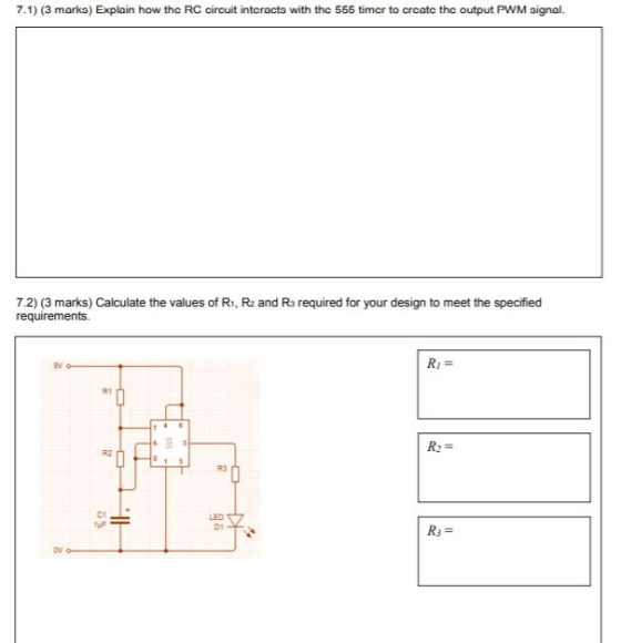
7.1) (3 marka) Explain how thc RC circuit intcracta with thc 555 timcr to crcatc the output PWM signal. 7.2) (3 marks) Calculate the values of R1, R2 and Ra required for your design to meet the specified requirements. ev R1 R2 R3 C1 LED D1 R3-
Homework Answers


Add Answer to:
ans, RA = 721.5 kohms, RB = 360.8 kohms, R3 = 3.5kohms as an example solution. Question 7 (6 marks) You have been given...
Question 8 (6 marks) You have been given a 555 Timer, an LED with Von-2V, a 9V battery that can comfortably supply 5mA...
 Question 8 (6 marks) You have been given a 555 Timer, an LED with Von-2V, a 9V battery that can comfortably supply 5mA of current without loss of voltage, a 1uF capacitor and access to any resistor values you want. Design a circuit that causes the LED to flash periodically once per second with a duty cycle of 75% Ensure that it does not draw more than 5mA of current from the battery (i.e 3mA of charging current and 2mA...
Can you Solve this question? III) (10/50) Given the following circuit 1) What is the nature of this circuit 2) Explain...
 Can you Solve this question?
III) (10/50) Given the following circuit 1) What is the nature of this circuit 2) Explain the principle of operation of this 555 multivibrator circuit 3) Draw the waveform of the output voltage Vo and V at pin 2 4) Find the expression of the pulse width W of the output voltage in terms of RA and C. 5) Given RA-1 00kΩand C 10μF. Calculate w 6) What are the differences between this circuit and...
Can you Solve this question?
III) (10/50) Given the following circuit 1) What is the nature of this circuit 2) Explain the principle of operation of this 555 multivibrator circuit 3) Draw the waveform of the output voltage Vo and V at pin 2 4) Find the expression of the pulse width W of the output voltage in terms of RA and C. 5) Given RA-1 00kΩand C 10μF. Calculate w 6) What are the differences between this circuit and...
Can you Solve this question? III) (10/50) Given the following circuit 1) What is the nature...
 Can you Solve this question?
III) (10/50) Given the following circuit 1) What is the nature of this circuit 2) Explain the principle of operation of this 555 multivibrator circuit 3) Draw the waveform of the output voltage Vo and V at pin 2 4) Find the expression of the pulse width W of the output voltage in terms of RA and C. 5) Given RA-1 00kΩand C 10μF. Calculate w 6) What are the differences between this circuit and...
Can you Solve this question?
III) (10/50) Given the following circuit 1) What is the nature of this circuit 2) Explain the principle of operation of this 555 multivibrator circuit 3) Draw the waveform of the output voltage Vo and V at pin 2 4) Find the expression of the pulse width W of the output voltage in terms of RA and C. 5) Given RA-1 00kΩand C 10μF. Calculate w 6) What are the differences between this circuit and...
Data Converters and Timing Circuits (20 marks) (a) For the timing circuit shown below, use a 1000pF capacitor and find the values of RA and RB that result in an oscillation frequency of 100KHz an...
 Data Converters and Timing Circuits (20 marks) (a) For the timing circuit shown below, use a 1000pF capacitor and find the values of RA and RB that result in an oscillation frequency of 100KHz and a duty cycle of 75% Reset 0.693 R,+2R,)C Discharge Outpat Threshold Trigger Ground Duty-Cle2R R,+2R, ar (b) The 4-Bit Weighted-Resistor DAC Converter shown below is to be expanded into an 8-bit device a. What are the required values of the additional resistors to be added?...
 Question 8 (6 marks) You have been given a 555 Timer, an LED with Von-2V, a 9V battery that can comfortably supply 5mA of current without loss of voltage, a 1uF capacitor and access to any resistor values you want. Design a circuit that causes the LED to flash periodically once per second with a duty cycle of 75% Ensure that it does not draw more than 5mA of current from the battery (i.e 3mA of charging current and 2mA...
 Can you Solve this question?
III) (10/50) Given the following circuit 1) What is the nature of this circuit 2) Explain the principle of operation of this 555 multivibrator circuit 3) Draw the waveform of the output voltage Vo and V at pin 2 4) Find the expression of the pulse width W of the output voltage in terms of RA and C. 5) Given RA-1 00kΩand C 10μF. Calculate w 6) What are the differences between this circuit and...
Can you Solve this question?
III) (10/50) Given the following circuit 1) What is the nature of this circuit 2) Explain the principle of operation of this 555 multivibrator circuit 3) Draw the waveform of the output voltage Vo and V at pin 2 4) Find the expression of the pulse width W of the output voltage in terms of RA and C. 5) Given RA-1 00kΩand C 10μF. Calculate w 6) What are the differences between this circuit and...
 Data Converters and Timing Circuits (20 marks) (a) For the timing circuit shown below, use a 1000pF capacitor and find the values of RA and RB that result in an oscillation frequency of 100KHz and a duty cycle of 75% Reset 0.693 R,+2R,)C Discharge Outpat Threshold Trigger Ground Duty-Cle2R R,+2R, ar (b) The 4-Bit Weighted-Resistor DAC Converter shown below is to be expanded into an 8-bit device a. What are the required values of the additional resistors to be added?...
Most questions answered within 3 hours.
-
Explain how each of the following three conditions could be a
red flag for a register...
asked 1 minute ago -
In a two-way factorial ANOVA, the final F-ratio for
factor AxB is determined by dividing _____...
asked 32 minutes ago -
Show your solutions for answer.
4. An aqueous solution contains 9.21 g of
K4Fe(CN)6 in a...
asked 2 minutes ago -
The random variable X has a uniform distribution with values
between 16 and 18. What is...
asked 11 minutes ago -
Evaluate each of the following transactions in terms of their
effect on assets, liabilities, and equity....
asked 10 minutes ago -
The amounts of nicotine in a certain brand of cigarette are
normally distributed with a mean...
asked 31 minutes ago -
The commercial lending department of First Bank made a
substantial loan to Alpha Company after obtaining...
asked 16 minutes ago -
For a reaction, reagents --->products, it's forwarding rate
(rate of products formation) is proportional to the...
asked 29 minutes ago -
5)
Typically,
there will need to be a rather high degree of coordination and
interaction among...
asked 25 minutes ago -
if the marginal revenue on each MRI is $2500, and the
marginal cost for each is...
asked 27 minutes ago -
What did Butler and Hobbes contribute to our understanding of
utilitarianism?
asked 32 minutes ago -
History
Lincoln's religious thought was almost exclusively shaped by his
Calvinist upbringing.
True
False
QUESTION 6...
asked 31 minutes ago