
Homework Answers


Add Answer to:
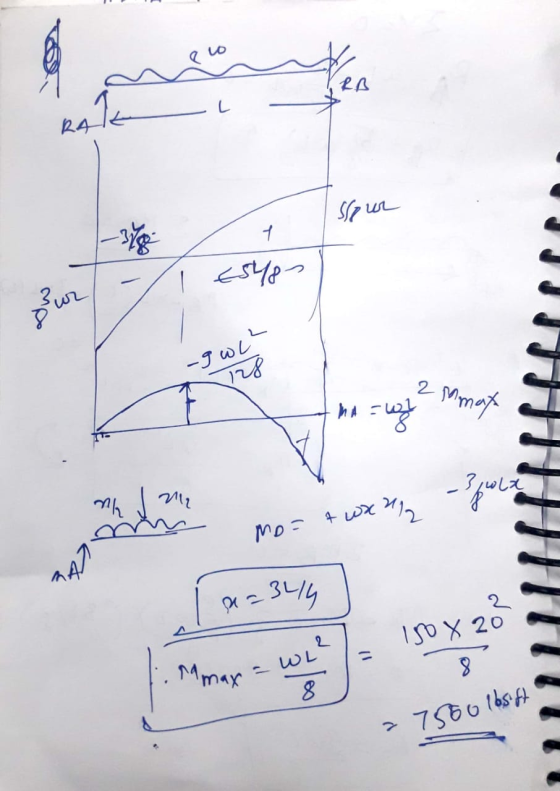
2-The 20 foot long cantilever beam shown in the figure is subjected to the loading shown...
The figure shown below is the cross section of a steel rectangular beam. The beam is subjected to transverse loading ap...
 The figure shown below is the cross section of a steel
rectangular beam. The beam is subjected to transverse loading
applied in the Y-direction.
Mark the location on the cross section that experiences
maximum normal stress.
FE CIVIL PRACTICE EXAM The figure shown below is the cross section of a steel rectangular beam. The beam is subjected to 64. transverse loading applied in the Y-direction Mark the location on the cross section that experiences maximum normal stress SIDE VIEW CROSS...
The figure shown below is the cross section of a steel
rectangular beam. The beam is subjected to transverse loading
applied in the Y-direction.
Mark the location on the cross section that experiences
maximum normal stress.
FE CIVIL PRACTICE EXAM The figure shown below is the cross section of a steel rectangular beam. The beam is subjected to 64. transverse loading applied in the Y-direction Mark the location on the cross section that experiences maximum normal stress SIDE VIEW CROSS...
Q5. The cantilever beam, AC, is subjected to the load case shown in Figure 5. For the loading shown, do the following: [10 Marks] a) Calculate the magnitude and direction of the reactions at A b) Usi...
 Q5. The cantilever beam, AC, is subjected to the load case shown in Figure 5. For the loading shown, do the following: [10 Marks] a) Calculate the magnitude and direction of the reactions at A b) Using the Macaulay function, determine the displacement in y of the point B of the beam (x 2.4 m from the support at A) [10 Marks] c) Determine the slope at B. [5 Marks] The beam has a Young's modulus of E-200 GPa and...
A beam with a square tubular cross section is subjected to the loading shown. The cross...
 A beam with a square tubular cross section is subjected to the
loading shown. The cross section of the beam is also
shown. Determine the maximum bending stress in the beam given:
L = 9 ft
P = 1,300 lb
do = 6 in
di = 5.4 in
1/3 We were unable to transcribe this imageA beam with a square tubular cross section is subjected to the loading shown. The cross section of the beam is also shown. Determine the...
A beam with a square tubular cross section is subjected to the
loading shown. The cross section of the beam is also
shown. Determine the maximum bending stress in the beam given:
L = 9 ft
P = 1,300 lb
do = 6 in
di = 5.4 in
1/3 We were unable to transcribe this imageA beam with a square tubular cross section is subjected to the loading shown. The cross section of the beam is also shown. Determine the...
7 A simply supported composite beam 12 ft. long is loaded by a force of 6...
 7 A simply supported composite beam 12 ft. long is loaded by a force of 6 k as shown. The cross-section of the composite beam consists of a wood block reinforced on its top and bottom by steel channels. The wood block has a modulus of elasticity of 2000 ksi while the steel channel has a modulus of elasticity of 30000 ksi. The steel channel has the following dimensions. Section Area Izz Centroid d tw bf in2in in.) Kin.) (in)...
If a cantilever beam is subjected to the following loading, and a cross section of the beam is provided.
 If a cantilever beam is subjected to the following loading, and a cross section of the beam is provided. a. determine the maximum bending stress in the beam. b Determine the absolute maximum shear stress in the beam.
A simply supported composite beam 12 ft. long is loaded by a force of 6 k...
 A simply supported composite beam 12 ft. long is loaded by a
force of 6 k as shown. The cross-section of the composite beam
consists of a wood block reinforced on its top and bottom by steel
channels. The wood block has a modulus of elasticity of 2000 ksi
while the steel channel has a modulus of elasticity of 30000 ksi.
The steel channel has the following dimensions.
Section
Area
(in2)
Izz
(in4)
Centroid
(in.)
d
(in.)
tw...
A simply supported composite beam 12 ft. long is loaded by a
force of 6 k as shown. The cross-section of the composite beam
consists of a wood block reinforced on its top and bottom by steel
channels. The wood block has a modulus of elasticity of 2000 ksi
while the steel channel has a modulus of elasticity of 30000 ksi.
The steel channel has the following dimensions.
Section
Area
(in2)
Izz
(in4)
Centroid
(in.)
d
(in.)
tw...
The cantilever beam is subjected to a concentrated load of P = 29 kips. The cross-sectional dimen...
 The cantilever beam is subjected to a concentrated load of
P = 29 kips. The cross-sectional dimensions of the
wide-flange shape are shown in the second figure. Assume
yH=3.4 in., yK=1.6 in.,
d=10.6 in., tw=0.323 in.,
tf=0.507 in., bf=6.12 in.
Determine:
The cantilever beam is subjected to a concentrated load of P 29 kips. The cross-sectional dimensions of the wide-flange shape are shown in the second figure. Assume y,-3.4 in., Ук_ 1.6 in., d-10.6 in., t,-0.323 in., tf-0.507 in., bf-6.12...
The cantilever beam is subjected to a concentrated load of
P = 29 kips. The cross-sectional dimensions of the
wide-flange shape are shown in the second figure. Assume
yH=3.4 in., yK=1.6 in.,
d=10.6 in., tw=0.323 in.,
tf=0.507 in., bf=6.12 in.
Determine:
The cantilever beam is subjected to a concentrated load of P 29 kips. The cross-sectional dimensions of the wide-flange shape are shown in the second figure. Assume y,-3.4 in., Ук_ 1.6 in., d-10.6 in., t,-0.323 in., tf-0.507 in., bf-6.12...
Problem 1 The composite shaft, consisting of aluminum, copper, and steel sections, is subjected to the loading shown. Determine the displacement of end A with respect to end D and the normal stress i...
 Problem 1 The composite shaft, consisting of aluminum, copper, and steel sections, is subjected to the loading shown. Determine the displacement of end A with respect to end D and the normal stress in each section. The cross- sectional area and modulus of elasticity for each section are shown in the figure. Neglect the size of the collars at B and C. Aluminum Copper 18(00)ksi E-29(10') ksi Steel -1010') ksi AB-0,09 in AcD 0.06 in Авс 0.1 2 i 2...
The cantilever beam is subjected to a concentrated load of P = 52 kips. The cross-sectional...
 The cantilever beam is
subjected to a concentrated load of P = 52 kips. The
cross-sectional dimensions of the wide-flange shape are shown in
the second figure. Assume yH = 3.2 in.,
yK = 1.8 in., d = 10.8 in.,
tw = 0.354 in., tf = 0.414
in., bf = 6.62 in. Determine:
(a) the shear stress τH at point H, which is located 3.2
in. below the centroid of the wide-flange shape.
(b) the maximum horizontal shear stress τmax...
The cantilever beam is
subjected to a concentrated load of P = 52 kips. The
cross-sectional dimensions of the wide-flange shape are shown in
the second figure. Assume yH = 3.2 in.,
yK = 1.8 in., d = 10.8 in.,
tw = 0.354 in., tf = 0.414
in., bf = 6.62 in. Determine:
(a) the shear stress τH at point H, which is located 3.2
in. below the centroid of the wide-flange shape.
(b) the maximum horizontal shear stress τmax...
The W10 × 15 cantilevered beam is made of A-36 steel and is subjected to the loading shown
 The W10 × 15 cantilevered beam is made of A-36 steel and is subjected to the loading shown. Suppose that w=2.5 kip/ft. E = 29(103) ksi and I = 68.9 in4.(Figure 1) Part A Determine the slope of the beam B, measured counterclockwise from the positive x axis. Express your answer using three significant figures. Part B Determine the displacement of the beam at B.
 The figure shown below is the cross section of a steel
rectangular beam. The beam is subjected to transverse loading
applied in the Y-direction.
Mark the location on the cross section that experiences
maximum normal stress.
FE CIVIL PRACTICE EXAM The figure shown below is the cross section of a steel rectangular beam. The beam is subjected to 64. transverse loading applied in the Y-direction Mark the location on the cross section that experiences maximum normal stress SIDE VIEW CROSS...
The figure shown below is the cross section of a steel
rectangular beam. The beam is subjected to transverse loading
applied in the Y-direction.
Mark the location on the cross section that experiences
maximum normal stress.
FE CIVIL PRACTICE EXAM The figure shown below is the cross section of a steel rectangular beam. The beam is subjected to 64. transverse loading applied in the Y-direction Mark the location on the cross section that experiences maximum normal stress SIDE VIEW CROSS...
 Q5. The cantilever beam, AC, is subjected to the load case shown in Figure 5. For the loading shown, do the following: [10 Marks] a) Calculate the magnitude and direction of the reactions at A b) Using the Macaulay function, determine the displacement in y of the point B of the beam (x 2.4 m from the support at A) [10 Marks] c) Determine the slope at B. [5 Marks] The beam has a Young's modulus of E-200 GPa and...
 A beam with a square tubular cross section is subjected to the
loading shown. The cross section of the beam is also
shown. Determine the maximum bending stress in the beam given:
L = 9 ft
P = 1,300 lb
do = 6 in
di = 5.4 in
1/3 We were unable to transcribe this imageA beam with a square tubular cross section is subjected to the loading shown. The cross section of the beam is also shown. Determine the...
A beam with a square tubular cross section is subjected to the
loading shown. The cross section of the beam is also
shown. Determine the maximum bending stress in the beam given:
L = 9 ft
P = 1,300 lb
do = 6 in
di = 5.4 in
1/3 We were unable to transcribe this imageA beam with a square tubular cross section is subjected to the loading shown. The cross section of the beam is also shown. Determine the...
 7 A simply supported composite beam 12 ft. long is loaded by a force of 6 k as shown. The cross-section of the composite beam consists of a wood block reinforced on its top and bottom by steel channels. The wood block has a modulus of elasticity of 2000 ksi while the steel channel has a modulus of elasticity of 30000 ksi. The steel channel has the following dimensions. Section Area Izz Centroid d tw bf in2in in.) Kin.) (in)...
 If a cantilever beam is subjected to the following loading, and a cross section of the beam is provided. a. determine the maximum bending stress in the beam. b Determine the absolute maximum shear stress in the beam.
 A simply supported composite beam 12 ft. long is loaded by a
force of 6 k as shown. The cross-section of the composite beam
consists of a wood block reinforced on its top and bottom by steel
channels. The wood block has a modulus of elasticity of 2000 ksi
while the steel channel has a modulus of elasticity of 30000 ksi.
The steel channel has the following dimensions.
Section
Area
(in2)
Izz
(in4)
Centroid
(in.)
d
(in.)
tw...
A simply supported composite beam 12 ft. long is loaded by a
force of 6 k as shown. The cross-section of the composite beam
consists of a wood block reinforced on its top and bottom by steel
channels. The wood block has a modulus of elasticity of 2000 ksi
while the steel channel has a modulus of elasticity of 30000 ksi.
The steel channel has the following dimensions.
Section
Area
(in2)
Izz
(in4)
Centroid
(in.)
d
(in.)
tw...
 The cantilever beam is subjected to a concentrated load of
P = 29 kips. The cross-sectional dimensions of the
wide-flange shape are shown in the second figure. Assume
yH=3.4 in., yK=1.6 in.,
d=10.6 in., tw=0.323 in.,
tf=0.507 in., bf=6.12 in.
Determine:
The cantilever beam is subjected to a concentrated load of P 29 kips. The cross-sectional dimensions of the wide-flange shape are shown in the second figure. Assume y,-3.4 in., Ук_ 1.6 in., d-10.6 in., t,-0.323 in., tf-0.507 in., bf-6.12...
The cantilever beam is subjected to a concentrated load of
P = 29 kips. The cross-sectional dimensions of the
wide-flange shape are shown in the second figure. Assume
yH=3.4 in., yK=1.6 in.,
d=10.6 in., tw=0.323 in.,
tf=0.507 in., bf=6.12 in.
Determine:
The cantilever beam is subjected to a concentrated load of P 29 kips. The cross-sectional dimensions of the wide-flange shape are shown in the second figure. Assume y,-3.4 in., Ук_ 1.6 in., d-10.6 in., t,-0.323 in., tf-0.507 in., bf-6.12...
 Problem 1 The composite shaft, consisting of aluminum, copper, and steel sections, is subjected to the loading shown. Determine the displacement of end A with respect to end D and the normal stress in each section. The cross- sectional area and modulus of elasticity for each section are shown in the figure. Neglect the size of the collars at B and C. Aluminum Copper 18(00)ksi E-29(10') ksi Steel -1010') ksi AB-0,09 in AcD 0.06 in Авс 0.1 2 i 2...
 The cantilever beam is
subjected to a concentrated load of P = 52 kips. The
cross-sectional dimensions of the wide-flange shape are shown in
the second figure. Assume yH = 3.2 in.,
yK = 1.8 in., d = 10.8 in.,
tw = 0.354 in., tf = 0.414
in., bf = 6.62 in. Determine:
(a) the shear stress τH at point H, which is located 3.2
in. below the centroid of the wide-flange shape.
(b) the maximum horizontal shear stress τmax...
The cantilever beam is
subjected to a concentrated load of P = 52 kips. The
cross-sectional dimensions of the wide-flange shape are shown in
the second figure. Assume yH = 3.2 in.,
yK = 1.8 in., d = 10.8 in.,
tw = 0.354 in., tf = 0.414
in., bf = 6.62 in. Determine:
(a) the shear stress τH at point H, which is located 3.2
in. below the centroid of the wide-flange shape.
(b) the maximum horizontal shear stress τmax...
Most questions answered within 3 hours.
-
A coach uses a new technique to train gymnasts. Seven
gymnasts were randomly selected and their...
asked 8 minutes ago -
While rotating the tires on your car you notice a rock [mass =
0.1 Kg] stuck...
asked 2 hours ago -
Using MARS simulator, write MIPS programs according to
the following scenarios: Receive a positive integer number...
asked 3 hours ago -
An object in front of a concave mirror has a real image that is
11.5 cm...
asked 4 hours ago -
Consider the reaction, C3 H8 + O2 --> CO2 + H2O. How many
moles of O2...
asked 5 hours ago -
You and your opponent both roll a fair die. If you both roll the
same number,...
asked 6 hours ago -
In a study of the accuracy of fast food drive-through orders,
Restaurant A had 257 accurate...
asked 6 hours ago -
Identify and describe in detail the four categories of
institutions that could be included in a...
asked 6 hours ago -
In python
class Customer:
def __init__(self, customer_id, last_name, first_name, phone_number, address):
self._customer_id = int(customer_id)
self._last_name =...
asked 6 hours ago -
What is an example of a limitation in implementing a new
ERP system and how it...
asked 6 hours ago -
In a section of 9.7cm of an artery with a radius of 2.6mm there
is a...
asked 6 hours ago -
the two carboxylic acid groups of aspartic acid have different
acidities with pKa values of 2.1...
asked 6 hours ago