
Homework Answers

Add Answer to:
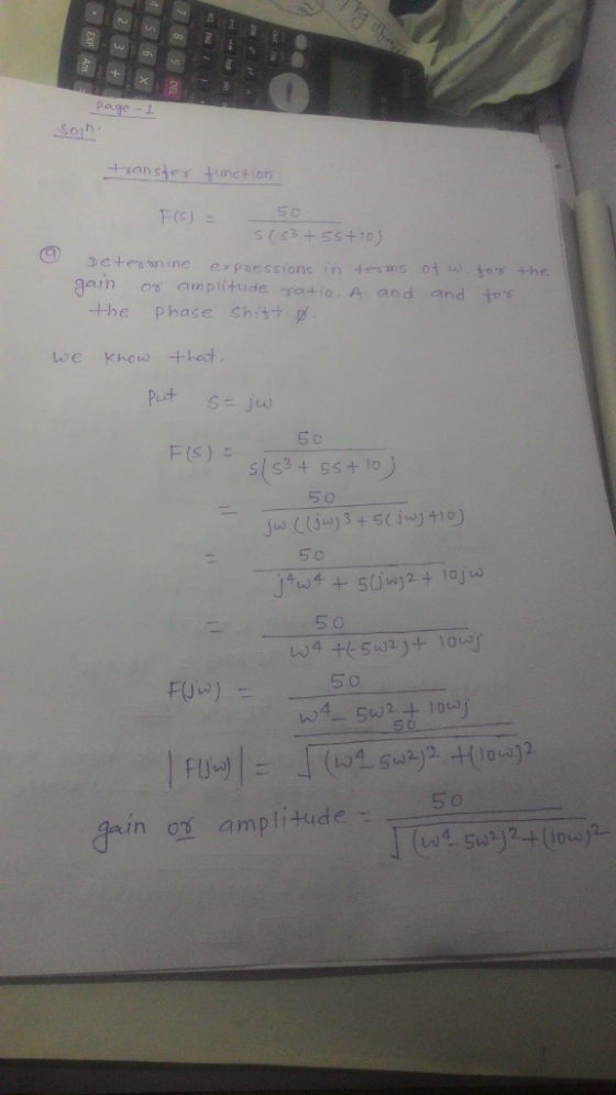
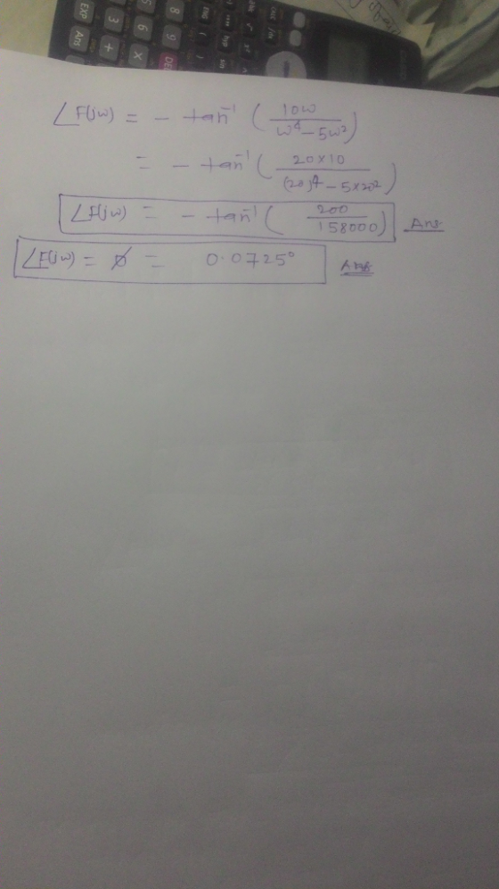
PROBLEM 3 (30 PTs) Given the following transfer function: 50 F(s) = s(83+6s+10) (a) Determine expressions,...
For the given transfer function: Ho-2where s 5 (s s (s +10) where s =j w...
 For the given transfer function: Ho-2where s 5 (s s (s +10) where s =j w Sketch the approximate Bode plots (amplitude and phase). Label all the amplitude values in db, phase values in degrees, the slopes in db/dec, and the corner frequencies in rad/sec.. a. b. If the gain of the transfer function given above, H(s), increased by a factor of 10 (from 5 to 50), what will happen to the approximate Bode plots (amplitude and phase) that you...
QUESTION 1 Given the transfer function for a control system: 10 G(s) (1 + s)(0.5s +...
 QUESTION 1 Given the transfer function for a control system: 10 G(s) (1 + s)(0.5s + 1) 1.1 Determine the polar representation: Magnitude (gain) and Phase (polar form), as a function of angular frequency w. Show steps. (6) 1.2 Make use of the table below and determine the Magnitude, Magnitude (in dB) and phase for the indicated frequencies. (rad/sec) G(jw)- Magnitude Gain [dB] = 20 log10 Magnitude Phase [degrees] 0.5 5 50
Problem 4 (50 pts): Consider the electrical circuit represented in figure, with R = 102, C...
 Problem 4 (50 pts): Consider the electrical circuit represented in figure, with R = 102, C = 1 F and L=1 H. Assume V (t) as input and i(t) as output E ER V.(t) a) (5 pts) Determine the differential equation of the system b) (5 pts) Find the transfer function of the system c) (20 pts) Write the symbolic expressions of magnitude and phase of the transfer function d) (20 pts) Determine the expression of steady-state response of the...
Problem 4: Given the transfer function, 25pts 25 H(s) S2+6s 25 (a) (b) (c) Fi Find...
 Problem 4: Given the transfer function, 25pts 25 H(s) S2+6s 25 (a) (b) (c) Fi Find Please put the units. Find the poles of the system. Is this system overdamped, underdamped, the settling time, peak time, percent overshoot, and rise time. undamped or critically damped. Explain. nd the state space representation in phase variable form of the above transfer function H(s)
50 400 Problem 3: A system has the transfer function: G(s) -8s+24s +800 3+80 Assuming time for this system is expressed in seconds,if the system is subjected to a periodic input of 4 sin cot, det...
 50 400 Problem 3: A system has the transfer function: G(s) -8s+24s +800 3+80 Assuming time for this system is expressed in seconds,if the system is subjected to a periodic input of 4 sin cot, determine: a) The frequency o where the amplitude of the output will be at its maximum. b) The functional expression for how the output amplitude varies with the input frequency, o. c) The functional expression for how the phase of the output with respect to...
singal and system QUESTION 5 [20 marks] Given transfer function of a networks H(s) transfer function...
 singal and
system
QUESTION 5 [20 marks] Given transfer function of a networks H(s) transfer function at w = 1000 rad/s. $10+ 52 +10005+7x10⁶ - Evaluate the [10 marks) b) Simplify and obtain the frequency response (magnitude and phase plots) of the 100(5+10) following transfer function H(s) s+10000 [6 marks] Sketch the magnitude and phase plots from (b) using Bode Plot Technique. [4 marks]
singal and
system
QUESTION 5 [20 marks] Given transfer function of a networks H(s) transfer function at w = 1000 rad/s. $10+ 52 +10005+7x10⁶ - Evaluate the [10 marks) b) Simplify and obtain the frequency response (magnitude and phase plots) of the 100(5+10) following transfer function H(s) s+10000 [6 marks] Sketch the magnitude and phase plots from (b) using Bode Plot Technique. [4 marks]
Problem 2 An RC circuit ( with an active component) has the following transfer function (where...
 Problem 2 An RC circuit ( with an active component) has the following transfer function (where R and Care positive) H(s) - Vout(8) _R|| R/10k12 Vin(8) 10KN 1 + $RC Where s = jw Find the value of the resistor and the value of the capacitor so that: for w = 0 rad/s, H(jw)lde = +12dB at f = 1kHz, |H(jw)lab = +9dB Problem 3 The transfer function of a circuit is given by H(S) = Vout(s) Vin(s) Where s...
Problem Three: Estimating a Transfer Function from a Bode Plot Based on the Bode Plot below,...
 Problem Three: Estimating a Transfer Function from a Bode Plot Based on the Bode Plot below, estimate the transfer function for this system. magnitude plot 20 0 2010g, ((w)) 40 -60 -80 10-2 10-1 10° 101 102 w (rad/s) phase plot 100 50 © -50 -100 102 10" 10° 102 10 101 (rad/s]
For the system transfer function given by: s +10 $2 x (82100.+10) 1. Identify each term in the tr...
 For the system transfer function given by: s +10 $2 x (82100.+10) 1. Identify each term in the transfer function (constant, poles, zeros) (a) For any constant terms, what is the dB magnitude? What is the phase angle? (b) For any real poles not at the origin, what is the break frequency? (c) For any real zeros not at the origin, what is the break frequency? 2. Give the value of the DB magnitude and phase angle at w =...
1. Find the transfer function Voda)/Vin(a) for the circuit shown in Figure 1 of the lab (where co...
 Please answer number 1
1. Find the transfer function Voda)/Vin(a) for the circuit shown in Figure 1 of the lab (where complex frequency variable s jo can be substituted for ease of analysis.) Calculate values for R and C such that the phase shift between the output and input is zero for an input frequency of 10kHz. What is the amplitude ratio (gain) of the output to the input at this frequency. 2. The RC network in figure 3 of...
Please answer number 1
1. Find the transfer function Voda)/Vin(a) for the circuit shown in Figure 1 of the lab (where complex frequency variable s jo can be substituted for ease of analysis.) Calculate values for R and C such that the phase shift between the output and input is zero for an input frequency of 10kHz. What is the amplitude ratio (gain) of the output to the input at this frequency. 2. The RC network in figure 3 of...
 For the given transfer function: Ho-2where s 5 (s s (s +10) where s =j w Sketch the approximate Bode plots (amplitude and phase). Label all the amplitude values in db, phase values in degrees, the slopes in db/dec, and the corner frequencies in rad/sec.. a. b. If the gain of the transfer function given above, H(s), increased by a factor of 10 (from 5 to 50), what will happen to the approximate Bode plots (amplitude and phase) that you...
 QUESTION 1 Given the transfer function for a control system: 10 G(s) (1 + s)(0.5s + 1) 1.1 Determine the polar representation: Magnitude (gain) and Phase (polar form), as a function of angular frequency w. Show steps. (6) 1.2 Make use of the table below and determine the Magnitude, Magnitude (in dB) and phase for the indicated frequencies. (rad/sec) G(jw)- Magnitude Gain [dB] = 20 log10 Magnitude Phase [degrees] 0.5 5 50
 Problem 4 (50 pts): Consider the electrical circuit represented in figure, with R = 102, C = 1 F and L=1 H. Assume V (t) as input and i(t) as output E ER V.(t) a) (5 pts) Determine the differential equation of the system b) (5 pts) Find the transfer function of the system c) (20 pts) Write the symbolic expressions of magnitude and phase of the transfer function d) (20 pts) Determine the expression of steady-state response of the...
 Problem 4: Given the transfer function, 25pts 25 H(s) S2+6s 25 (a) (b) (c) Fi Find Please put the units. Find the poles of the system. Is this system overdamped, underdamped, the settling time, peak time, percent overshoot, and rise time. undamped or critically damped. Explain. nd the state space representation in phase variable form of the above transfer function H(s)
 50 400 Problem 3: A system has the transfer function: G(s) -8s+24s +800 3+80 Assuming time for this system is expressed in seconds,if the system is subjected to a periodic input of 4 sin cot, determine: a) The frequency o where the amplitude of the output will be at its maximum. b) The functional expression for how the output amplitude varies with the input frequency, o. c) The functional expression for how the phase of the output with respect to...
 singal and
system
QUESTION 5 [20 marks] Given transfer function of a networks H(s) transfer function at w = 1000 rad/s. $10+ 52 +10005+7x10⁶ - Evaluate the [10 marks) b) Simplify and obtain the frequency response (magnitude and phase plots) of the 100(5+10) following transfer function H(s) s+10000 [6 marks] Sketch the magnitude and phase plots from (b) using Bode Plot Technique. [4 marks]
singal and
system
QUESTION 5 [20 marks] Given transfer function of a networks H(s) transfer function at w = 1000 rad/s. $10+ 52 +10005+7x10⁶ - Evaluate the [10 marks) b) Simplify and obtain the frequency response (magnitude and phase plots) of the 100(5+10) following transfer function H(s) s+10000 [6 marks] Sketch the magnitude and phase plots from (b) using Bode Plot Technique. [4 marks]
 Problem 2 An RC circuit ( with an active component) has the following transfer function (where R and Care positive) H(s) - Vout(8) _R|| R/10k12 Vin(8) 10KN 1 + $RC Where s = jw Find the value of the resistor and the value of the capacitor so that: for w = 0 rad/s, H(jw)lde = +12dB at f = 1kHz, |H(jw)lab = +9dB Problem 3 The transfer function of a circuit is given by H(S) = Vout(s) Vin(s) Where s...
 Problem Three: Estimating a Transfer Function from a Bode Plot Based on the Bode Plot below, estimate the transfer function for this system. magnitude plot 20 0 2010g, ((w)) 40 -60 -80 10-2 10-1 10° 101 102 w (rad/s) phase plot 100 50 © -50 -100 102 10" 10° 102 10 101 (rad/s]
 For the system transfer function given by: s +10 $2 x (82100.+10) 1. Identify each term in the transfer function (constant, poles, zeros) (a) For any constant terms, what is the dB magnitude? What is the phase angle? (b) For any real poles not at the origin, what is the break frequency? (c) For any real zeros not at the origin, what is the break frequency? 2. Give the value of the DB magnitude and phase angle at w =...
 Please answer number 1
1. Find the transfer function Voda)/Vin(a) for the circuit shown in Figure 1 of the lab (where complex frequency variable s jo can be substituted for ease of analysis.) Calculate values for R and C such that the phase shift between the output and input is zero for an input frequency of 10kHz. What is the amplitude ratio (gain) of the output to the input at this frequency. 2. The RC network in figure 3 of...
Please answer number 1
1. Find the transfer function Voda)/Vin(a) for the circuit shown in Figure 1 of the lab (where complex frequency variable s jo can be substituted for ease of analysis.) Calculate values for R and C such that the phase shift between the output and input is zero for an input frequency of 10kHz. What is the amplitude ratio (gain) of the output to the input at this frequency. 2. The RC network in figure 3 of...
Most questions answered within 3 hours.
-
Myca Corp. has a project with the following cash flows. What is
the value of the...
asked 4 minutes ago -
When an object moves through a fluid, the fluid exerts a viscous
force F on the...
asked 1 hour ago -
Why did the observed chemistry of thallium mislead Mendelev to
place the group 13 element (Tl)...
asked 3 hours ago -
A sine wave signal is displayed on the screen of an
oscilloscope. 6 peak-to-peak divisions are...
asked 5 hours ago -
a
1500 kg car accelerates from 0 to 25 m / s in 21.0s. How much...
asked 6 hours ago -
Calculate the molarity of each of the following solutions:
(a) 30.5 g of ethanol (C2H5OH) in...
asked 6 hours ago -
1 Refer to the build-borrow-or-buy framework as a decision tree
for the Adidas company. Identify a...
asked 7 hours ago -
Problem 2: The Problem of Social Cost. A Rancher and Farmer live
side-by-side to each other....
asked 8 hours ago -
a uniform bar of weight 40N is 4 meter long. weights
on 60N and 100N are...
asked 8 hours ago -
Define Diet counceling? What are the
responsibilities of a counselor?
asked 10 hours ago -
Hey im just confused about how to put the ' A angle n' and ' S...
asked 10 hours ago -
A short essay about the WSJ article on Oreo versus Hydrox.
asked 10 hours ago