please do as soon as possible an use PSPICE I just need the pspice part

please use Pspice
use pspice to slove


Homework Answers
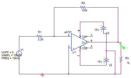
Non inverting amplifier:
Gain=1+R2/R1= 1+ 100k/2.2k
= 45.45
Circuit diagram:
Ac analysis:
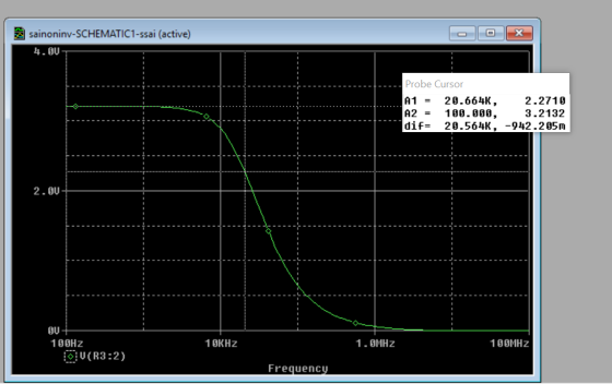
Cut off frequency =20.66khz
Transient analysis(unsaturated response)

Transient analysis:(saturated response)

Gain =v0/vin=30/4=7.5
but the expected gain is 45.45
Add Answer to:
please do as soon as possible an use PSPICE I just need
the pspice part
please...
how to draw this circuit in pspice PRE-LAB Resistors 150kQ, 180k2, 220k2, 270k2, 330k2, 39k02, 470k2, 560kQ Part A. I...
 how to draw this circuit in pspice
PRE-LAB Resistors 150kQ, 180k2, 220k2, 270k2, 330k2, 39k02, 470k2, 560kQ Part A. Inverting Amplifier. Deliverables - PSpice schematie and graphs 1. Draw the circuit for a standard inverting amplifier (see text). You can leave the resistors variables for now: Ai 2. Choose the resistor values from components available for this lab in the list above to give a gain between 5 and 10. Use values of 5.6 kΩ or greater. Record the resistor...
how to draw this circuit in pspice
PRE-LAB Resistors 150kQ, 180k2, 220k2, 270k2, 330k2, 39k02, 470k2, 560kQ Part A. Inverting Amplifier. Deliverables - PSpice schematie and graphs 1. Draw the circuit for a standard inverting amplifier (see text). You can leave the resistors variables for now: Ai 2. Choose the resistor values from components available for this lab in the list above to give a gain between 5 and 10. Use values of 5.6 kΩ or greater. Record the resistor...
Part I: Inverting Amplifier Procedure: 1. Build the circuit model for inverting amplifier in PSpice with...
 Part I: Inverting Amplifier Procedure: 1. Build the circuit model for inverting amplifier in PSpice with the following parameters: Ri = 5 k 2, R2 = 20 ks2, V+ = 10 V, V-=-10 V. 2. Hand calculates the theoretical closed loop gain Vout/Vin of the circuit model. 3. Generate a triangular waveform for Vin with the amplitude of 1 V and the period of 1 ms. 4. Run simulation. a. Set circuit model parameters. i.e., for voltage source: click VPWL...
PLEASE SHOW ALL WORK AND TO FOLLOW DIRECTIONS. PLEASE USE PSPICE. STUDENT ID= 7220849 3. Using...
 PLEASE SHOW ALL WORK AND TO FOLLOW DIRECTIONS. PLEASE USE
PSPICE.
STUDENT ID= 7220849
3. Using a DC Sweep analysis to graph currents and voltages Let R1 through R4 equivalent to the digits 1 through 4 in your StudentID in k 2 (use 10 k12 for a digit of 0). • For example, if your StudentID is 9870654 then R1 =9 KS2, R2 =8 kN, R3 = 7k2 and R4 = 10k12 A. Analyze Circuit 3 by hand to determine...
PLEASE SHOW ALL WORK AND TO FOLLOW DIRECTIONS. PLEASE USE
PSPICE.
STUDENT ID= 7220849
3. Using a DC Sweep analysis to graph currents and voltages Let R1 through R4 equivalent to the digits 1 through 4 in your StudentID in k 2 (use 10 k12 for a digit of 0). • For example, if your StudentID is 9870654 then R1 =9 KS2, R2 =8 kN, R3 = 7k2 and R4 = 10k12 A. Analyze Circuit 3 by hand to determine...
Resistors 2700 3300 3900 4700 56002 Capacitors 1.OnF 1.5nF 2.2nF Inductors 2.7mH 1500 1800 2200 6800...
 Resistors 2700 3300 3900 4700 56002 Capacitors 1.OnF 1.5nF 2.2nF Inductors 2.7mH 1500 1800 2200 6800 8200 1.0kn 1.2k2 1.5k 1.8k 22.2k02 2.7k 2 3.3nF 4.7nF 6.8nF 3.3k 3.9k 4.7kn 5.6k 26.8k0 8.2k210k 2 12kΩ 10nF 15F 22nF 15kΩ 18kQ2 22kΩ 27kg 33kg 39k 47kg 56kΩ 33nF 47nF 68nF 68k 82kg 100k 120ko 150k 150k 180k 220ko 100nF 150nF 270kn 330kn 390kW 470kn 560kn 680k0 820ko 1.0M Table 1 In this lab, you will design and build Passive & Active...
please do part d only: Replace R1 with a series combination of R1 and a capacitor. Assume Vin = V0sinwt. determine the magnitude of vout/v0 as a function of w and sketch, noting values at critical r...
 please do part d only: Replace R1 with a series combination of
R1 and a capacitor. Assume Vin = V0sinwt. determine the magnitude
of vout/v0 as a function of w and sketch, noting values at critical
regions of the graph. what kind of circuit is this?
1. [50 points total] Consider the circuit model for a non- inverting operational amplifier circuit: Vin a. [10 points] Identify all of the nodes in the circuit diagram -how many are there? How many...
please do part d only: Replace R1 with a series combination of
R1 and a capacitor. Assume Vin = V0sinwt. determine the magnitude
of vout/v0 as a function of w and sketch, noting values at critical
regions of the graph. what kind of circuit is this?
1. [50 points total] Consider the circuit model for a non- inverting operational amplifier circuit: Vin a. [10 points] Identify all of the nodes in the circuit diagram -how many are there? How many...
please I need details l and....Debate Club | Offic A) Theoretical Design Design a common emitter BJT amplifier with the following requirements: -Rin-10 K2, and Ro-45 ㏀ (Neglect the Early voltage...
 please I need details
l and....Debate Club | Offic A) Theoretical Design Design a common emitter BJT amplifier with the following requirements: -Rin-10 K2, and Ro-45 ㏀ (Neglect the Early voltage Effect) Vo/Vsig- Gv-40 VIV or 32 dB " VCC-9 V V, IC-1mA, VCE-3.25V and β-100 RL-40 kQ, Rsige I ka, R 1-3R2, and C1-C2-1 μF Voc RC C2 R1 Rsig C1 RL R2 RE B) Verify your design using Orcad Capture Pspice by doing 1) AC sweep (frequency response):...
please I need details
l and....Debate Club | Offic A) Theoretical Design Design a common emitter BJT amplifier with the following requirements: -Rin-10 K2, and Ro-45 ㏀ (Neglect the Early voltage Effect) Vo/Vsig- Gv-40 VIV or 32 dB " VCC-9 V V, IC-1mA, VCE-3.25V and β-100 RL-40 kQ, Rsige I ka, R 1-3R2, and C1-C2-1 μF Voc RC C2 R1 Rsig C1 RL R2 RE B) Verify your design using Orcad Capture Pspice by doing 1) AC sweep (frequency response):...
Circuit Analysis: Need help writing this into MATLAB. I do not need it in paper I need help putting it into MATLAB. * DO NOT WRITE ON PAPER* Please use MATLAB and post your code. Thank you. My work c...
 Circuit Analysis: Need help writing this into MATLAB. I do not
need it in paper I need help putting it into MATLAB. * DO NOT WRITE
ON PAPER* Please use MATLAB and post your code. Thank you.
My work completed. Please help me in make code for the above
circuit ^.
Here is my work for Part 3 that is needed to complete this part
4. ( could not solve the last part)
Part 4. AC Solution by Phasor Analysis...
Circuit Analysis: Need help writing this into MATLAB. I do not
need it in paper I need help putting it into MATLAB. * DO NOT WRITE
ON PAPER* Please use MATLAB and post your code. Thank you.
My work completed. Please help me in make code for the above
circuit ^.
Here is my work for Part 3 that is needed to complete this part
4. ( could not solve the last part)
Part 4. AC Solution by Phasor Analysis...
I just need the last part h) Please show all your work. I'll rate. Thank you...
 I just need the last part h) Please show all your work. I'll
rate. Thank you in advance!
Physics 1122 Quiz 4E – Exp. 7 October 22 - 24, 2019 DIRECTIONS: Work the problem. You must show all work to receive credit, and you must return this sheet. The problem is worth 20 points. If you have to construct a graph, use the graph paper provided in the laboratory. Solve the problem using only symbolic algebra and then report numerical...
I just need the last part h) Please show all your work. I'll
rate. Thank you in advance!
Physics 1122 Quiz 4E – Exp. 7 October 22 - 24, 2019 DIRECTIONS: Work the problem. You must show all work to receive credit, and you must return this sheet. The problem is worth 20 points. If you have to construct a graph, use the graph paper provided in the laboratory. Solve the problem using only symbolic algebra and then report numerical...
 how to draw this circuit in pspice
PRE-LAB Resistors 150kQ, 180k2, 220k2, 270k2, 330k2, 39k02, 470k2, 560kQ Part A. Inverting Amplifier. Deliverables - PSpice schematie and graphs 1. Draw the circuit for a standard inverting amplifier (see text). You can leave the resistors variables for now: Ai 2. Choose the resistor values from components available for this lab in the list above to give a gain between 5 and 10. Use values of 5.6 kΩ or greater. Record the resistor...
how to draw this circuit in pspice
PRE-LAB Resistors 150kQ, 180k2, 220k2, 270k2, 330k2, 39k02, 470k2, 560kQ Part A. Inverting Amplifier. Deliverables - PSpice schematie and graphs 1. Draw the circuit for a standard inverting amplifier (see text). You can leave the resistors variables for now: Ai 2. Choose the resistor values from components available for this lab in the list above to give a gain between 5 and 10. Use values of 5.6 kΩ or greater. Record the resistor...
 Part I: Inverting Amplifier Procedure: 1. Build the circuit model for inverting amplifier in PSpice with the following parameters: Ri = 5 k 2, R2 = 20 ks2, V+ = 10 V, V-=-10 V. 2. Hand calculates the theoretical closed loop gain Vout/Vin of the circuit model. 3. Generate a triangular waveform for Vin with the amplitude of 1 V and the period of 1 ms. 4. Run simulation. a. Set circuit model parameters. i.e., for voltage source: click VPWL...
 PLEASE SHOW ALL WORK AND TO FOLLOW DIRECTIONS. PLEASE USE
PSPICE.
STUDENT ID= 7220849
3. Using a DC Sweep analysis to graph currents and voltages Let R1 through R4 equivalent to the digits 1 through 4 in your StudentID in k 2 (use 10 k12 for a digit of 0). • For example, if your StudentID is 9870654 then R1 =9 KS2, R2 =8 kN, R3 = 7k2 and R4 = 10k12 A. Analyze Circuit 3 by hand to determine...
PLEASE SHOW ALL WORK AND TO FOLLOW DIRECTIONS. PLEASE USE
PSPICE.
STUDENT ID= 7220849
3. Using a DC Sweep analysis to graph currents and voltages Let R1 through R4 equivalent to the digits 1 through 4 in your StudentID in k 2 (use 10 k12 for a digit of 0). • For example, if your StudentID is 9870654 then R1 =9 KS2, R2 =8 kN, R3 = 7k2 and R4 = 10k12 A. Analyze Circuit 3 by hand to determine...
 Resistors 2700 3300 3900 4700 56002 Capacitors 1.OnF 1.5nF 2.2nF Inductors 2.7mH 1500 1800 2200 6800 8200 1.0kn 1.2k2 1.5k 1.8k 22.2k02 2.7k 2 3.3nF 4.7nF 6.8nF 3.3k 3.9k 4.7kn 5.6k 26.8k0 8.2k210k 2 12kΩ 10nF 15F 22nF 15kΩ 18kQ2 22kΩ 27kg 33kg 39k 47kg 56kΩ 33nF 47nF 68nF 68k 82kg 100k 120ko 150k 150k 180k 220ko 100nF 150nF 270kn 330kn 390kW 470kn 560kn 680k0 820ko 1.0M Table 1 In this lab, you will design and build Passive & Active...
 please do part d only: Replace R1 with a series combination of
R1 and a capacitor. Assume Vin = V0sinwt. determine the magnitude
of vout/v0 as a function of w and sketch, noting values at critical
regions of the graph. what kind of circuit is this?
1. [50 points total] Consider the circuit model for a non- inverting operational amplifier circuit: Vin a. [10 points] Identify all of the nodes in the circuit diagram -how many are there? How many...
please do part d only: Replace R1 with a series combination of
R1 and a capacitor. Assume Vin = V0sinwt. determine the magnitude
of vout/v0 as a function of w and sketch, noting values at critical
regions of the graph. what kind of circuit is this?
1. [50 points total] Consider the circuit model for a non- inverting operational amplifier circuit: Vin a. [10 points] Identify all of the nodes in the circuit diagram -how many are there? How many...
 please I need details
l and....Debate Club | Offic A) Theoretical Design Design a common emitter BJT amplifier with the following requirements: -Rin-10 K2, and Ro-45 ㏀ (Neglect the Early voltage Effect) Vo/Vsig- Gv-40 VIV or 32 dB " VCC-9 V V, IC-1mA, VCE-3.25V and β-100 RL-40 kQ, Rsige I ka, R 1-3R2, and C1-C2-1 μF Voc RC C2 R1 Rsig C1 RL R2 RE B) Verify your design using Orcad Capture Pspice by doing 1) AC sweep (frequency response):...
please I need details
l and....Debate Club | Offic A) Theoretical Design Design a common emitter BJT amplifier with the following requirements: -Rin-10 K2, and Ro-45 ㏀ (Neglect the Early voltage Effect) Vo/Vsig- Gv-40 VIV or 32 dB " VCC-9 V V, IC-1mA, VCE-3.25V and β-100 RL-40 kQ, Rsige I ka, R 1-3R2, and C1-C2-1 μF Voc RC C2 R1 Rsig C1 RL R2 RE B) Verify your design using Orcad Capture Pspice by doing 1) AC sweep (frequency response):...
 Circuit Analysis: Need help writing this into MATLAB. I do not
need it in paper I need help putting it into MATLAB. * DO NOT WRITE
ON PAPER* Please use MATLAB and post your code. Thank you.
My work completed. Please help me in make code for the above
circuit ^.
Here is my work for Part 3 that is needed to complete this part
4. ( could not solve the last part)
Part 4. AC Solution by Phasor Analysis...
Circuit Analysis: Need help writing this into MATLAB. I do not
need it in paper I need help putting it into MATLAB. * DO NOT WRITE
ON PAPER* Please use MATLAB and post your code. Thank you.
My work completed. Please help me in make code for the above
circuit ^.
Here is my work for Part 3 that is needed to complete this part
4. ( could not solve the last part)
Part 4. AC Solution by Phasor Analysis...
 I just need the last part h) Please show all your work. I'll
rate. Thank you in advance!
Physics 1122 Quiz 4E – Exp. 7 October 22 - 24, 2019 DIRECTIONS: Work the problem. You must show all work to receive credit, and you must return this sheet. The problem is worth 20 points. If you have to construct a graph, use the graph paper provided in the laboratory. Solve the problem using only symbolic algebra and then report numerical...
I just need the last part h) Please show all your work. I'll
rate. Thank you in advance!
Physics 1122 Quiz 4E – Exp. 7 October 22 - 24, 2019 DIRECTIONS: Work the problem. You must show all work to receive credit, and you must return this sheet. The problem is worth 20 points. If you have to construct a graph, use the graph paper provided in the laboratory. Solve the problem using only symbolic algebra and then report numerical...
Most questions answered within 3 hours.
-
Minitab Problem: Take the Lake Hume June rainfall data and find
use the processes outlined in...
asked 40 minutes ago -
X Company is trying to decide whether to continue using old
equipment to make Product A...
asked 41 minutes ago -
IN PYTHON ONLY !! Program 2: Re-work
program #5 (WeeklyHours) from the previous assignment such that...
asked 1 hour ago -
The average length of time between arrivals at a turnpike
toll-booth is 26 seconds. What is...
asked 2 hours ago -
(a) A piston at 6.1 atm contains a gas that occupies a volume of
3.5 L....
asked 4 hours ago -
Please answer true or false. Words
cannot be changed or added in to make it true...
asked 4 hours ago -
An empty test tube weighs 15.923 grams. Then,
MgCl2•6H2O is added into the test tube. After...
asked 4 hours ago -
Assume memory access is 10 units of time and disk access is
10000 units of time....
asked 4 hours ago -
1. Are all good samples random?
2. Magazines often report surveys giving statistics such as “63%...
asked 4 hours ago -
Under all the various types of market structures, firms
must eventually earn some economic profits for...
asked 4 hours ago -
Consider the following fitness regime for a single locus trait
with two co-dominant alleles: w11 =...
asked 4 hours ago -
A large cable company reports the following.
80% of its customers subscribe to its cable TV...
asked 4 hours ago