
Homework Answers


Add Answer to:
AISI 1018 HR
Section #2 (80p) 035 CD 1018 HR Q1. The figure shows a shaft...
The figure shows a shaft mounted in bearings at A and D and having pulleys at B and C. The forces shown acting on the pully surfaces represent the belt tensions.
 Problem 1: The figure shows a shaft mounted in bearings at A and D and having pulleys at B and C. The forces shown acting on the pully surfaces represent the belt tensions. The shaft is to be made of AISI 1040 HR steel. Using a conservative failure theory with a design factor of 2, determine the minimum shaft diameter to avoid yielding.
The figure shows a 1.5 inch diameter shaft mounted in bearings at A and D and...
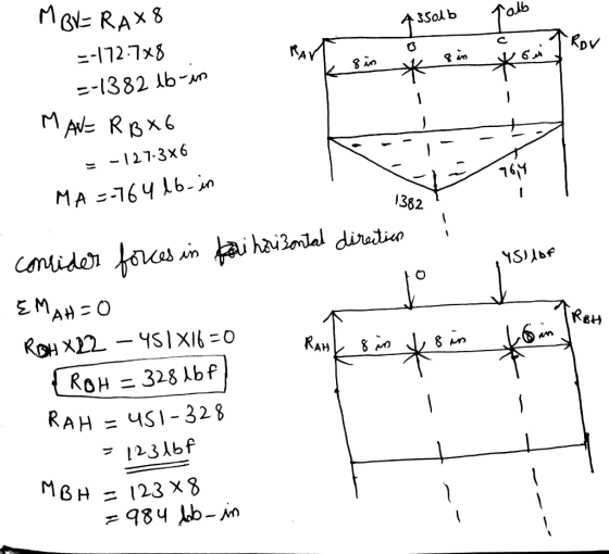
 The figure shows a 1.5 inch diameter shaft mounted in bearings at A and D and having pulleys at B and C. The forces shown acting on the pulley surfaces represent the belt tensions. Considering static loading, determine the principal stresses in the shaft? 6-in D. 300 lbf 50 lbf 27 lbf 360 lbfID 8-in D.6 in B8 in A 8 in
A countershaft, made of AISI 1035 CD steel, carrying two V-belt pulleys is shown in the figure. P...
 A countershaft, made of AISI 1035 CD steel, carrying two V-belt pulleys is shown in the figure. Pulley A receives power from a motor through a belt with the belt tensions shown. The power is transmitted through the shaft and delivered to the belt on pulley B. Assume the belt tension on the loose side at B is 25 percent of the tension on the tight side (F2 - 0.25 F) 1) Based on the equations for yielding conditions discussed...
The figure above shows a shaft mounted in bearings A and D and having pulleys at B and C.
 The figure above shows a shaft mounted in bearings A and D and having pulleys at B and C. The shaft is 20 mm in diameter and made of AISI 1020 CD steel. The forces shown acting on the pulley surfaces represent the belt tensions. The shaft is concerned with yielding and fatigue failure. [Stress analysis) (1) Draw the free body diagrams and find reaction forces at A and D in the xy and xz planes. (2) Draw the shear force and moment...
Required information The figure shows a shaft mounted in bearings at A and D and having...
 Required information The figure shows a shaft mounted in bearings at A and D and having pulleys at B and C. The forces shown acting on the pulley surfaces represent the belt tensions. The shaft is to be made of AISI 1035 CD steel. The design factor is 2. The value of FB1= 240 lb, FB2= 40 lb, FC1= 47.256 lb, and Fc2= 313.974 lb. NOTE: This is a multi-part question. Once an answer is submitted, you will be unable...
The shaft shown in the figure is machined from AISI 1040 CD steel and is supported in rolling bearings at A and B.
 The shaft shown in the figure is machined from AISI 1040 CD steel and is supported in rolling bearings at A and B. The applied forces F1 = 1500 lbf and F2 = 3000 lbf are coming off of gears located at respective positions. The shaft rotates at 2000 rpm while transmitting 50hp between the gears. Determine the minimum fatigue factor of safety based on achieving infinite life using Modified- Goodman theory. If infinite life is not predicted, estimate the...
 The figure shows a 1.5 inch diameter shaft mounted in bearings at A and D and having pulleys at B and C. The forces shown acting on the pulley surfaces represent the belt tensions. Considering static loading, determine the principal stresses in the shaft? 6-in D. 300 lbf 50 lbf 27 lbf 360 lbfID 8-in D.6 in B8 in A 8 in
 A countershaft, made of AISI 1035 CD steel, carrying two V-belt pulleys is shown in the figure. Pulley A receives power from a motor through a belt with the belt tensions shown. The power is transmitted through the shaft and delivered to the belt on pulley B. Assume the belt tension on the loose side at B is 25 percent of the tension on the tight side (F2 - 0.25 F) 1) Based on the equations for yielding conditions discussed...
 Required information The figure shows a shaft mounted in bearings at A and D and having pulleys at B and C. The forces shown acting on the pulley surfaces represent the belt tensions. The shaft is to be made of AISI 1035 CD steel. The design factor is 2. The value of FB1= 240 lb, FB2= 40 lb, FC1= 47.256 lb, and Fc2= 313.974 lb. NOTE: This is a multi-part question. Once an answer is submitted, you will be unable...
Most questions answered within 3 hours.
-
A regression equation that describes the relationship between
the amount of the bill ($) at a...
asked 38 minutes ago -
exercise on VSEPR and molecular structrue.
octahedral
SeCl62-
TeCl62-
ClF62-
distorted
SeF62–
IF6–
asked 1 hour ago -
284 mL of a 0.52 M potassium hydroxide solution is added to 467
mL of a...
asked 1 hour ago -
Little’s Law: Val d’Costa is a world famous ski village in the
French Alps. Because of...
asked 1 hour ago -
Find the absolute error D for the calculation if A + B/C=D A=
9.4 +/- 0.4...
asked 2 hours ago -
New Air Heating and Cooling, manufactures furnaces and central
air units. The company pride itself on...
asked 2 hours ago -
A coach uses a new technique to train gymnasts. Seven
gymnasts were randomly selected and their...
asked 4 hours ago -
While rotating the tires on your car you notice a rock [mass =
0.1 Kg] stuck...
asked 6 hours ago -
Using MARS simulator, write MIPS programs according to
the following scenarios: Receive a positive integer number...
asked 8 hours ago -
An object in front of a concave mirror has a real image that is
11.5 cm...
asked 8 hours ago -
Consider the reaction, C3 H8 + O2 --> CO2 + H2O. How many
moles of O2...
asked 10 hours ago -
You and your opponent both roll a fair die. If you both roll the
same number,...
asked 10 hours ago