
Homework Answers

Add Answer to:
Calculate the deflection and slope at B and the deflection at D for the uniform beam...
The beam is shown in the figure below. Use the slope-deflection method. The support Ais pinned,...
 The beam is shown in the figure below. Use the slope-deflection method. The support Ais pinned, support B is a roller, and support C is fixed. Assume El = 21537 kNm2. The support at B settles by 73 mm (downwards). The segment AB is subjected to a uniformly distributed load w= 11 kN/m. The segment BC is subjected to a point load P = 91 KN. Enter the digit one in the answer box. The link will be provided on...
For the shown beam, find the vertical deflection at point D by using: Assume B is a hinge, Member...
 can you show the solution in details and clear hand written ?
please
For the shown beam, find the vertical deflection at point D by using: Assume B is a hinge, Member size is W360x110 by using Double integration method Notice that please W-6 60 kN 18 kN/mm 2 m. 2.5 m. 2.5 m. 3 m. ni
For the shown beam, find the vertical deflection at point D by using: Assume B is a hinge, Member size is W360x110 by...
can you show the solution in details and clear hand written ?
please
For the shown beam, find the vertical deflection at point D by using: Assume B is a hinge, Member size is W360x110 by using Double integration method Notice that please W-6 60 kN 18 kN/mm 2 m. 2.5 m. 2.5 m. 3 m. ni
For the shown beam, find the vertical deflection at point D by using: Assume B is a hinge, Member size is W360x110 by...
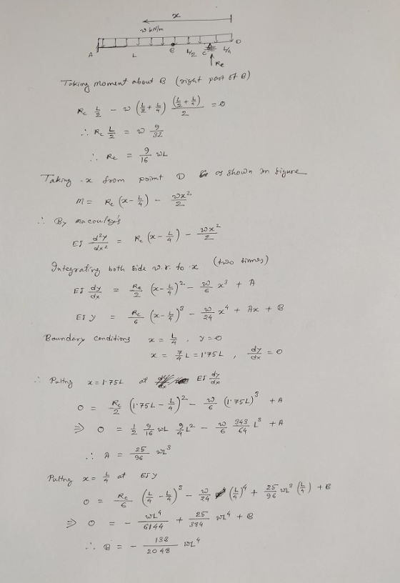
2. For the beam and loading shown, determine the slope and deflection at point B. Where:...
 2. For the beam and loading shown, determine the slope and deflection at point B. Where: w = 2 kN/m, L = 2 m, E = 200 GPa, and I = 1.708 x 10 m. B 1/2- 1/2
QUESTION3 As shown in Figure Q3, a cantilever beam ABCD is used to support uniform load 4 KN/m al...
 QUESTION3 As shown in Figure Q3, a cantilever beam ABCD is used to support uniform load 4 KN/m along span BC and momvent at point A. U'sing Macaulay's method, L express the deflection of the beam stiffness in terms of E 6 marks) ii. determine the deflection at point C, and (2 marks) ili. calculate the slope at end A (2 marks) 3 kNm Figure QWRajah S3
QUESTION3 As shown in Figure Q3, a cantilever beam ABCD is used to...
QUESTION3 As shown in Figure Q3, a cantilever beam ABCD is used to support uniform load 4 KN/m along span BC and momvent at point A. U'sing Macaulay's method, L express the deflection of the beam stiffness in terms of E 6 marks) ii. determine the deflection at point C, and (2 marks) ili. calculate the slope at end A (2 marks) 3 kNm Figure QWRajah S3
QUESTION3 As shown in Figure Q3, a cantilever beam ABCD is used to...
Use the Conjugate Beam Method to compute the slope and deflection at points B and C...
 Use the Conjugate Beam Method to compute the slope and
deflection at points B and C for the beam given below. EI =
constant. Express answers as positive quantities with correct units
in the numerator terms, and with appropriate directions
Problem 1. Use the Conjugate Beam Method to compute the slope and deflection at points B and C for the beam given below. El constant. Express answers as positive quantities with correct units in the numerator terms, and with appropriate...
Use the Conjugate Beam Method to compute the slope and
deflection at points B and C for the beam given below. EI =
constant. Express answers as positive quantities with correct units
in the numerator terms, and with appropriate directions
Problem 1. Use the Conjugate Beam Method to compute the slope and deflection at points B and C for the beam given below. El constant. Express answers as positive quantities with correct units in the numerator terms, and with appropriate...
Need a solution for slope-deflection method Question 2 (20 marks) Use the Slope-Deflection Method to analyse...
 Need a solution for slope-deflection method
Question 2 (20 marks) Use the Slope-Deflection Method to analyse the frame in Figure 2. Plot diagrams for internal forces (M, V and N). Indicate magnitudes at all significant points. The bending stiffness of members is indicated in the figure. Neglect the effect of shear and axial forces on the structural deformations. 90 kNm 24 kN/m B v 64 kN a, 4m 2m ទឹក 9m Sm A 2ET ZEL 201 6m E] &m E1...
Need a solution for slope-deflection method
Question 2 (20 marks) Use the Slope-Deflection Method to analyse the frame in Figure 2. Plot diagrams for internal forces (M, V and N). Indicate magnitudes at all significant points. The bending stiffness of members is indicated in the figure. Neglect the effect of shear and axial forces on the structural deformations. 90 kNm 24 kN/m B v 64 kN a, 4m 2m ទឹក 9m Sm A 2ET ZEL 201 6m E] &m E1...
A continuous beam ABC shown in Figure 2 is fixed at A. Supports at B and C are rollers. A uniform distributed load 40kN...
 A continuous beam ABC shown in Figure 2 is fixed at A. Supports at B and C are rollers. A uniform distributed load 40kN/m is applied force acts downward on the span of BC as shown in Figure 2. The EI of the beam is over the span of AB and a 60kN constant (a) Determine the internal moments at A and B using the slope-deflection method [10 marks] (b) Draw the bending values of bending (c) Sketch the deformed...
Q.2.[40 pts] For the frame shown, use Slope-deflection method to determine the end-moments of each member...
 Q.2.[40 pts] For the frame shown, use Slope-deflection method to determine the end-moments of each member only. Support A is fixed. Support C is pin. 10 KN 12 kN/m C 71 B 2 EI 3 m 2E1 M AB = FEM AB + (202 + 0g - 34 ap) L 2E1 = FEM + (@A + 20g – 34 AB) L ЗЕІ 40 KN M BA BA 3 m A 6 m
QUESTION 4 (25 marks) A simply supported beam is loaded by an uniform distributed load, wkN/m, over the span of the beam, L, as shown in Figure Q4. (a) Determine the end reactions at point A and...
 QUESTION 4 (25 marks) A simply supported beam is loaded by an uniform distributed load, wkN/m, over the span of the beam, L, as shown in Figure Q4. (a) Determine the end reactions at point A and B in terms of w and L. (4 marks) (b) At an arbitrary point, x, express the internal mom (c) Show that the deflection curve of the beam under the loading situation is ent, M(x), in x, w, and L. (5 marks) 24EI...
For the beam shown, use the Conjugate Beam Method to determine a) The deflection at F,...
 For the beam shown, use the Conjugate Beam Method to determine a) The deflection at F, b) The slopes on both sides of the hinge at C. 90 KN 160 kN.m E B с D F 2 m m 2 m 2 m 2 m EI = Constant
 The beam is shown in the figure below. Use the slope-deflection method. The support Ais pinned, support B is a roller, and support C is fixed. Assume El = 21537 kNm2. The support at B settles by 73 mm (downwards). The segment AB is subjected to a uniformly distributed load w= 11 kN/m. The segment BC is subjected to a point load P = 91 KN. Enter the digit one in the answer box. The link will be provided on...
 can you show the solution in details and clear hand written ?
please
For the shown beam, find the vertical deflection at point D by using: Assume B is a hinge, Member size is W360x110 by using Double integration method Notice that please W-6 60 kN 18 kN/mm 2 m. 2.5 m. 2.5 m. 3 m. ni
For the shown beam, find the vertical deflection at point D by using: Assume B is a hinge, Member size is W360x110 by...
can you show the solution in details and clear hand written ?
please
For the shown beam, find the vertical deflection at point D by using: Assume B is a hinge, Member size is W360x110 by using Double integration method Notice that please W-6 60 kN 18 kN/mm 2 m. 2.5 m. 2.5 m. 3 m. ni
For the shown beam, find the vertical deflection at point D by using: Assume B is a hinge, Member size is W360x110 by...
 2. For the beam and loading shown, determine the slope and deflection at point B. Where: w = 2 kN/m, L = 2 m, E = 200 GPa, and I = 1.708 x 10 m. B 1/2- 1/2
 QUESTION3 As shown in Figure Q3, a cantilever beam ABCD is used to support uniform load 4 KN/m along span BC and momvent at point A. U'sing Macaulay's method, L express the deflection of the beam stiffness in terms of E 6 marks) ii. determine the deflection at point C, and (2 marks) ili. calculate the slope at end A (2 marks) 3 kNm Figure QWRajah S3
QUESTION3 As shown in Figure Q3, a cantilever beam ABCD is used to...
QUESTION3 As shown in Figure Q3, a cantilever beam ABCD is used to support uniform load 4 KN/m along span BC and momvent at point A. U'sing Macaulay's method, L express the deflection of the beam stiffness in terms of E 6 marks) ii. determine the deflection at point C, and (2 marks) ili. calculate the slope at end A (2 marks) 3 kNm Figure QWRajah S3
QUESTION3 As shown in Figure Q3, a cantilever beam ABCD is used to...
 Use the Conjugate Beam Method to compute the slope and
deflection at points B and C for the beam given below. EI =
constant. Express answers as positive quantities with correct units
in the numerator terms, and with appropriate directions
Problem 1. Use the Conjugate Beam Method to compute the slope and deflection at points B and C for the beam given below. El constant. Express answers as positive quantities with correct units in the numerator terms, and with appropriate...
Use the Conjugate Beam Method to compute the slope and
deflection at points B and C for the beam given below. EI =
constant. Express answers as positive quantities with correct units
in the numerator terms, and with appropriate directions
Problem 1. Use the Conjugate Beam Method to compute the slope and deflection at points B and C for the beam given below. El constant. Express answers as positive quantities with correct units in the numerator terms, and with appropriate...
 Need a solution for slope-deflection method
Question 2 (20 marks) Use the Slope-Deflection Method to analyse the frame in Figure 2. Plot diagrams for internal forces (M, V and N). Indicate magnitudes at all significant points. The bending stiffness of members is indicated in the figure. Neglect the effect of shear and axial forces on the structural deformations. 90 kNm 24 kN/m B v 64 kN a, 4m 2m ទឹក 9m Sm A 2ET ZEL 201 6m E] &m E1...
Need a solution for slope-deflection method
Question 2 (20 marks) Use the Slope-Deflection Method to analyse the frame in Figure 2. Plot diagrams for internal forces (M, V and N). Indicate magnitudes at all significant points. The bending stiffness of members is indicated in the figure. Neglect the effect of shear and axial forces on the structural deformations. 90 kNm 24 kN/m B v 64 kN a, 4m 2m ទឹក 9m Sm A 2ET ZEL 201 6m E] &m E1...
 A continuous beam ABC shown in Figure 2 is fixed at A. Supports at B and C are rollers. A uniform distributed load 40kN/m is applied force acts downward on the span of BC as shown in Figure 2. The EI of the beam is over the span of AB and a 60kN constant (a) Determine the internal moments at A and B using the slope-deflection method [10 marks] (b) Draw the bending values of bending (c) Sketch the deformed...
 Q.2.[40 pts] For the frame shown, use Slope-deflection method to determine the end-moments of each member only. Support A is fixed. Support C is pin. 10 KN 12 kN/m C 71 B 2 EI 3 m 2E1 M AB = FEM AB + (202 + 0g - 34 ap) L 2E1 = FEM + (@A + 20g – 34 AB) L ЗЕІ 40 KN M BA BA 3 m A 6 m
 QUESTION 4 (25 marks) A simply supported beam is loaded by an uniform distributed load, wkN/m, over the span of the beam, L, as shown in Figure Q4. (a) Determine the end reactions at point A and B in terms of w and L. (4 marks) (b) At an arbitrary point, x, express the internal mom (c) Show that the deflection curve of the beam under the loading situation is ent, M(x), in x, w, and L. (5 marks) 24EI...
 For the beam shown, use the Conjugate Beam Method to determine a) The deflection at F, b) The slopes on both sides of the hinge at C. 90 KN 160 kN.m E B с D F 2 m m 2 m 2 m 2 m EI = Constant
Most questions answered within 3 hours.
-
.13 : Assume that we make an enhancement to a computer that
improves some mode of...
asked 26 seconds from now -
4)
Find the tension in an elevator cable if the 1000 kg elevator is
descending with...
asked 5 minutes ago -
A random sample of 51 newborn babies was taken at the Hospital.
The sample mean was...
asked 3 minutes ago -
Industry standards suggest that 16% of new vehicles require
warranty service within the first year. Jones...
asked 14 minutes ago -
1) Comment of this statement: “A compiler transforms high-level
language statements directly into object codes”.
asked 17 minutes ago -
Calculate the molality, mole-fraction and percent mass of 28.9M
HF at 25 degrees Celcius of the...
asked 26 minutes ago -
A developmental psychologist believes that children raised in
bilingual families will have higher verbal fluency at...
asked 33 minutes ago -
A fast food meal has 5660 kJ of energy. A person uses energy at
a rate...
asked 45 minutes ago -
The pKb for a generic amine(R-NH2)) in
aqueous solution is 6.30. What is its pKa?
asked 47 minutes ago -
The following reactions have the indicated equilibrium constants
at a particular temperature: N2(g) + O2(g) ⇌...
asked 49 minutes ago -
Please Help ASAP.
1Consider the below code which iterates over a linked
list of n nodes...
asked 1 hour ago -
Determine the air to fuel ratio of:
Canadian natural gas, with 93.9% methane, 4.2% ethane, 0.3%...
asked 1 hour ago