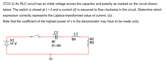
An RLC circuit has an initial voltage across the capacitor and polarity as marked on the circuit shown below. The switch is closed at t = 0 and a current i(t) is assumed to flow clockwise in the circuit. Determine which expression correctly represents the Laplace-transformed value of current, i(s). Note that the coefficient of the highest power of s in the denominator may have to be made unity.
Homework Answers

Add Answer to:
An RLC circuit has an initial voltage across the capacitor and
polarity as marked on the...
Learning Goal: To analyze an RC circuit to determine the initial voltage across a capacitor, the...
 Learning Goal: To analyze an RC circuit to determine the initial voltage across a capacitor, the time constant, and the expression for the natural response of the capacitor voltage, and then to find other circuit quantities such as current,voltage, power, or energy. The natural response of an RC circuit is the response of the capacitor voltage to the sudden removal of a DC source. When this occurs, the capacitor releases its stored energy Figure < 10121〉 t 0 V. Figure...
The initial voltage across the capacitor is 0 V. At time t=0, the switch is closed
 The initial voltage across the capacitor is 0 V. At time t=0, the switch is closed a) What is the time constant for this circuit? b) What is the final voltage across the 50 capacitor? c) What is the expression for the voltage across the 50 capacitor? d) Sketch the waveform for . e) What is the maximum instantaneous current that will flow through the capacitor? f) When will the voltage reach 5.0 V?
4) RLC parallel circuits R1 R2 500 1E-2 1E-8 U2 1500 In the above circuit, the...
 4) RLC parallel circuits R1 R2 500 1E-2 1E-8 U2 1500 In the above circuit, the source turns on at t-0 with a voltage of 10V. Additionally, switch U1 is closed and switch U2 is open. At 15E-6 s switch U1 opens and switch U2 closes. The source also tuns off at 15E-6 s a. Use Laplace analysis to determine the voltage across the capacitor as a function of time for 0<t< 15E-6 (s) b. Use Laplace analysis to determine...
For the circuit shown, find the following: a) v(0+), the voltage across the capacitor right after...
 For the circuit shown, find the following: a) v(0+), the voltage across the capacitor right after the switch closes. b) v), the voltage across the capacitor after the switch has been closed for a long time. c) v(T), the voltage across the capacitor after one time constant. 2. 3 S2 I(t) 12 V+ 6 Ω 0.5 F u(t) 3. For the circuit above, write the differential equation for t > 0.
9. For the given circuit, if the initial voltage across the capacitor is vc(0*) = 0,...
 9. For the given circuit, if the initial voltage across the capacitor is vc(0*) = 0, find an expression for the voltrage across the capacitor as a function of time and graph voltage versus time. R= 100 k2 w v=100 V uc) C = 0.01 uF 10. If a 100-F capacitance is initially charged to 1000V and at t=0, it is connected to a 1-ka resistance, at what time has 50 percent of the initial energy stored in the capacitance...
The capacitor in the circuit is initially uncharged, when at t = 0 s, the switch is closed. At what time is the voltage across the capacitor equal to 7.5 V?
 The capacitor in the circuit is initially uncharged, when at t = 0 s, the switch is closed. At what time is the voltage across the capacitor equal to 7.5 V?
An RC circuit is connected across a DC voltage source through an open switch. The switch...
An RC circuit is connected across a DC voltage source through an open switch. The switch is closed at t = 0 s. Which of the following is a correct statement regarding the circuit? The capacitor charges to its maximum value in one time constant. The resistor and the capacitor share the applied voltage equally as a function of time. The current flows through the circuit even after the capacitor is fully charged. Once the capacitor is fully charged, there...
Only need the last question 5 thanks! 3) RLC Parallel Circuits: Differential Equations and Laplace U2...
 Only need the last question 5 thanks!
3) RLC Parallel Circuits: Differential Equations and Laplace U2 U1 TOPEN 0 TCLOSE 0 L1 R1 0.15H C1 2E-8F 11 10E-3 2 10E-3 At t 0, U1 closes and U2 opens. 3.1: What is the intial (t-0+) current through the capacitor? What is the initial (t=0+) voltage across the capacitor? 3.2: What is the DC steady state current though the capacitor ast goes to infinity? 3.3: Find the current through the CAPACITOR as...
Only need the last question 5 thanks!
3) RLC Parallel Circuits: Differential Equations and Laplace U2 U1 TOPEN 0 TCLOSE 0 L1 R1 0.15H C1 2E-8F 11 10E-3 2 10E-3 At t 0, U1 closes and U2 opens. 3.1: What is the intial (t-0+) current through the capacitor? What is the initial (t=0+) voltage across the capacitor? 3.2: What is the DC steady state current though the capacitor ast goes to infinity? 3.3: Find the current through the CAPACITOR as...
An RC circuit is connected across an ideal DC voltage source through an open switch. The...
 An RC circuit is connected across an ideal DC voltage source through an open switch. The switch is closed at time t = 0 s. Which of the following statements regarding the circuit are correct The capacitor charges to its maximum value in one time constant and the current is zero at that time. The potential difference across the resistor and the potential difference across the capacitor are always equal. The potential difference across the resistor is always greater than...
1. RLC Circuits Revisited. The first example of a RLC circuit illustrates the use of circuit...
 1. RLC Circuits Revisited. The first example of a RLC circuit illustrates the use of circuit elements in the s domain to represent initial conditions and a forced response. Next an example of sinusoidal excitation will follow where the transient response and steady state response are combined into one response waveform.. Transient RLC Circuit with Initial Conditions. Consider the RLC circuit below in Figure 7.14 which has two DC sources (Vco and V) applied before and after a switch is...
 Learning Goal: To analyze an RC circuit to determine the initial voltage across a capacitor, the time constant, and the expression for the natural response of the capacitor voltage, and then to find other circuit quantities such as current,voltage, power, or energy. The natural response of an RC circuit is the response of the capacitor voltage to the sudden removal of a DC source. When this occurs, the capacitor releases its stored energy Figure < 10121〉 t 0 V. Figure...
 4) RLC parallel circuits R1 R2 500 1E-2 1E-8 U2 1500 In the above circuit, the source turns on at t-0 with a voltage of 10V. Additionally, switch U1 is closed and switch U2 is open. At 15E-6 s switch U1 opens and switch U2 closes. The source also tuns off at 15E-6 s a. Use Laplace analysis to determine the voltage across the capacitor as a function of time for 0<t< 15E-6 (s) b. Use Laplace analysis to determine...
 For the circuit shown, find the following: a) v(0+), the voltage across the capacitor right after the switch closes. b) v), the voltage across the capacitor after the switch has been closed for a long time. c) v(T), the voltage across the capacitor after one time constant. 2. 3 S2 I(t) 12 V+ 6 Ω 0.5 F u(t) 3. For the circuit above, write the differential equation for t > 0.
 9. For the given circuit, if the initial voltage across the capacitor is vc(0*) = 0, find an expression for the voltrage across the capacitor as a function of time and graph voltage versus time. R= 100 k2 w v=100 V uc) C = 0.01 uF 10. If a 100-F capacitance is initially charged to 1000V and at t=0, it is connected to a 1-ka resistance, at what time has 50 percent of the initial energy stored in the capacitance...
 Only need the last question 5 thanks!
3) RLC Parallel Circuits: Differential Equations and Laplace U2 U1 TOPEN 0 TCLOSE 0 L1 R1 0.15H C1 2E-8F 11 10E-3 2 10E-3 At t 0, U1 closes and U2 opens. 3.1: What is the intial (t-0+) current through the capacitor? What is the initial (t=0+) voltage across the capacitor? 3.2: What is the DC steady state current though the capacitor ast goes to infinity? 3.3: Find the current through the CAPACITOR as...
Only need the last question 5 thanks!
3) RLC Parallel Circuits: Differential Equations and Laplace U2 U1 TOPEN 0 TCLOSE 0 L1 R1 0.15H C1 2E-8F 11 10E-3 2 10E-3 At t 0, U1 closes and U2 opens. 3.1: What is the intial (t-0+) current through the capacitor? What is the initial (t=0+) voltage across the capacitor? 3.2: What is the DC steady state current though the capacitor ast goes to infinity? 3.3: Find the current through the CAPACITOR as...
 An RC circuit is connected across an ideal DC voltage source through an open switch. The switch is closed at time t = 0 s. Which of the following statements regarding the circuit are correct The capacitor charges to its maximum value in one time constant and the current is zero at that time. The potential difference across the resistor and the potential difference across the capacitor are always equal. The potential difference across the resistor is always greater than...
 1. RLC Circuits Revisited. The first example of a RLC circuit illustrates the use of circuit elements in the s domain to represent initial conditions and a forced response. Next an example of sinusoidal excitation will follow where the transient response and steady state response are combined into one response waveform.. Transient RLC Circuit with Initial Conditions. Consider the RLC circuit below in Figure 7.14 which has two DC sources (Vco and V) applied before and after a switch is...
Most questions answered within 3 hours.
-
Discounting cash flows involves:
A. taking the cash discount offered on a trade merchandise
B. estimating...
asked 52 seconds from now -
1. Your grandmother has invested $4000 in a mutual fund each
year on your birthday (she...
asked 41 seconds ago -
HELP WITH SAS
Run the following DATA step to create a SAS data set called
ABC_CORP....
asked 13 minutes ago -
A researcher wishes to study the cumulative effects of several
combinations of HIV drugs. There are...
asked 33 minutes ago -
How
to make a simple game of whack a mole in pygame
asked 16 minutes ago -
Write a c/c++ program to read a list of students from a file and
create a...
asked 25 minutes ago -
Identify two different methods for collecting data in
qualitative research. What are the benefits and challenges...
asked 26 minutes ago -
I am suppose to have my array before the main class but I am
getting the...
asked 28 minutes ago -
Your task is to design the page table for the 32bit Pentium
microprocessor. Answer the following...
asked 34 minutes ago -
The Paradise Shoes Company has estimated its weekly TVC function
from data collected over the past...
asked 33 minutes ago -
Although Epicurus advocates pursuing pleasure for the
good life, discuss a few reasons why he does...
asked 50 minutes ago -
Problem 1: Present entries to record the selected transactions
described below:
(a)
Issued $2,790,000 of 5-year,...
asked 57 minutes ago