
Homework Answers

Problem #17 In the following circuit,L2-5.6 mH, R-5 Ohm, C-8.6uF, angular frequency w 10000 rad/s. The...
 Problem #17 In the following circuit,L2-5.6 mH, R-5 Ohm, C-8.6uF, angular frequency w 10000 rad/s. The amplitude of the current through the resistor Ris 8.7 A. What is the amplitude of the current through C? [ 12 Submit Answer Tries 0/5 Problem #18 In the following circuit, 12- 8.7 mH, R-6.6 Ohm, angular frequency w 1000 rad/s, VB(t)- 2.8 cos(1000t). What is the circuit current waveform (t) _ cos_ t+ )? R ve ZL2 cos
L1 s] CI ?2 s2 In the circuit, the amplitude and phase of the voltage source...
 L1 s] CI ?2 s2 In the circuit, the amplitude and phase of the voltage source Vs1 are 120 V and 0.4 rad, those of the voltage source Vs2 are 230 V and 0.5 rad, the voltage frequency is 20 kHz; 36 mH, L2 20 mH, C1 2.5 nF R1-3 kOhm, R2 7 kOhm, R36 kOhm, L1 Find the impedance of inductor L1 Real part of impedance (Ohm) Submit Answer Tries 0/3 Impaginary part of impedance (Ohm): Submit Answer Tries...
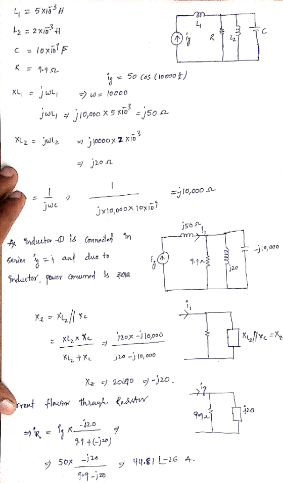
In the following circuit, L2= 9.9 mH, R= 1.6 Ohm, angular frequency w= 1000 rad/s, VB(t)=...
 In the following circuit, L2= 9.9 mH, R= 1.6 Ohm, angular
frequency w= 1000 rad/s, VB(t)= 5 cos(1000t). What is the circuit
current waveform i(t)= ____cos(___ t + ___)?
i(t)= _____*cos(_____*t+_____).
し2
In the following circuit, L2= 9.9 mH, R= 1.6 Ohm, angular
frequency w= 1000 rad/s, VB(t)= 5 cos(1000t). What is the circuit
current waveform i(t)= ____cos(___ t + ___)?
i(t)= _____*cos(_____*t+_____).
し2
Matlab Code if available Problem 04 mm us(0 In the circuit, the voltage source Vs(t) frequency,...
 Matlab Code if available
Problem 04 mm us(0 In the circuit, the voltage source Vs(t) frequency, amplitude and phase are 22 kHz, 10 V and 0.25 rad correspondingly; Rs=4 Ohm, Ri=12 Ohm, R2=9 Ohm, R3=2 Ohm, L1=0.11 mH, L2=0.13 mH, C= 1.4 uF ("u"="micro"). Part A. Using any appropriate techniques, find the parameters of Thevenin equivalent circuit with respect to the ports "a" and "b". Present the Thevenin source in the polar form and the Thevenin impedance in the algebraic...
Matlab Code if available
Problem 04 mm us(0 In the circuit, the voltage source Vs(t) frequency, amplitude and phase are 22 kHz, 10 V and 0.25 rad correspondingly; Rs=4 Ohm, Ri=12 Ohm, R2=9 Ohm, R3=2 Ohm, L1=0.11 mH, L2=0.13 mH, C= 1.4 uF ("u"="micro"). Part A. Using any appropriate techniques, find the parameters of Thevenin equivalent circuit with respect to the ports "a" and "b". Present the Thevenin source in the polar form and the Thevenin impedance in the algebraic...
Part A Find the average power delivered by the ideal current source in the circuit in...
 Part A Find the average power delivered by the ideal current source in the circuit in the figure if ig-4 cos 5000t mA.(Figure 1) Express your answer with the appropriate units. P. Value Units igure 1 of 1 Submit Request Answer Provide Feedback 500 Ω 1000 Ω 100 mH 160 nF
Problem 05 In R Out For the circuit above, answer the following questions. 1. Derive the formula ...
 Please Help!
Problem 05 In R Out For the circuit above, answer the following questions. 1. Derive the formula for the transfer function angular resonant frequency omega_res (enter the right hand side part of the formula only) Use exactly same notations for L,C and R as in the circuit diagram. Hints for solving the problem. (1) Ignore trivial solution omega_res 0 (2) In case obtaining the resonant frequency using the condition imag(H)0 fails, try finding the resonant frequency using impedance...
Please Help!
Problem 05 In R Out For the circuit above, answer the following questions. 1. Derive the formula for the transfer function angular resonant frequency omega_res (enter the right hand side part of the formula only) Use exactly same notations for L,C and R as in the circuit diagram. Hints for solving the problem. (1) Ignore trivial solution omega_res 0 (2) In case obtaining the resonant frequency using the condition imag(H)0 fails, try finding the resonant frequency using impedance...
Problem 10.7 Consider the circuit in (Figure 1). Part A Find the average power delivered by...
 Problem 10.7 Consider the circuit in (Figure 1). Part A Find the average power delivered by the ideal current source in the circuit if 2g = 70 cos 1250 mA. Express your answer to three significant figures and include the appropriate units. LO ЦА 2 ? Figure 1 of 1 > P= 96 w Submit Previous Answers Request Answer 5 ΚΩ * Incorrect; Try Again; One attempt remaining 8H 80 nF Provide Feedback
VO) L1 L2 Line VO LI Power Calculations Learning Goal: In this tutorial, you will practice...
 VO) L1 L2 Line VO LI Power Calculations Learning Goal: In this tutorial, you will practice the calculation of power in circuits containing loads, including the effects of non-ideal transmission lines, and practice how to improve the power factor for an entire system. Many appliances (eg., hair dryers, coffee makers, and refrigerators) and industrial loads are powered by AC sources. The ability to be able to calculate their power needs is important in a number of situations. Before completing this...
In a series L-R-C circuit, the components have the following values: L = 20.0 mH, C...
 In a series L-R-C circuit, the components have the following values: L = 20.0 mH, C = 140 nF, and R = 350 Ohm. The generator has an rms voltage 120 V and a frequency of 1.25 kHz. Part A Determine the average power supplied by the generator. P = W Submit My Answers Give Up Part B Determine the average power dissipated in the resistor. PR = W Submit My Answers Give Up
 Problem #17 In the following circuit,L2-5.6 mH, R-5 Ohm, C-8.6uF, angular frequency w 10000 rad/s. The amplitude of the current through the resistor Ris 8.7 A. What is the amplitude of the current through C? [ 12 Submit Answer Tries 0/5 Problem #18 In the following circuit, 12- 8.7 mH, R-6.6 Ohm, angular frequency w 1000 rad/s, VB(t)- 2.8 cos(1000t). What is the circuit current waveform (t) _ cos_ t+ )? R ve ZL2 cos
 L1 s] CI ?2 s2 In the circuit, the amplitude and phase of the voltage source Vs1 are 120 V and 0.4 rad, those of the voltage source Vs2 are 230 V and 0.5 rad, the voltage frequency is 20 kHz; 36 mH, L2 20 mH, C1 2.5 nF R1-3 kOhm, R2 7 kOhm, R36 kOhm, L1 Find the impedance of inductor L1 Real part of impedance (Ohm) Submit Answer Tries 0/3 Impaginary part of impedance (Ohm): Submit Answer Tries...
 In the following circuit, L2= 9.9 mH, R= 1.6 Ohm, angular
frequency w= 1000 rad/s, VB(t)= 5 cos(1000t). What is the circuit
current waveform i(t)= ____cos(___ t + ___)?
i(t)= _____*cos(_____*t+_____).
し2
In the following circuit, L2= 9.9 mH, R= 1.6 Ohm, angular
frequency w= 1000 rad/s, VB(t)= 5 cos(1000t). What is the circuit
current waveform i(t)= ____cos(___ t + ___)?
i(t)= _____*cos(_____*t+_____).
し2
 Matlab Code if available
Problem 04 mm us(0 In the circuit, the voltage source Vs(t) frequency, amplitude and phase are 22 kHz, 10 V and 0.25 rad correspondingly; Rs=4 Ohm, Ri=12 Ohm, R2=9 Ohm, R3=2 Ohm, L1=0.11 mH, L2=0.13 mH, C= 1.4 uF ("u"="micro"). Part A. Using any appropriate techniques, find the parameters of Thevenin equivalent circuit with respect to the ports "a" and "b". Present the Thevenin source in the polar form and the Thevenin impedance in the algebraic...
Matlab Code if available
Problem 04 mm us(0 In the circuit, the voltage source Vs(t) frequency, amplitude and phase are 22 kHz, 10 V and 0.25 rad correspondingly; Rs=4 Ohm, Ri=12 Ohm, R2=9 Ohm, R3=2 Ohm, L1=0.11 mH, L2=0.13 mH, C= 1.4 uF ("u"="micro"). Part A. Using any appropriate techniques, find the parameters of Thevenin equivalent circuit with respect to the ports "a" and "b". Present the Thevenin source in the polar form and the Thevenin impedance in the algebraic...
 Part A Find the average power delivered by the ideal current source in the circuit in the figure if ig-4 cos 5000t mA.(Figure 1) Express your answer with the appropriate units. P. Value Units igure 1 of 1 Submit Request Answer Provide Feedback 500 Ω 1000 Ω 100 mH 160 nF
 Please Help!
Problem 05 In R Out For the circuit above, answer the following questions. 1. Derive the formula for the transfer function angular resonant frequency omega_res (enter the right hand side part of the formula only) Use exactly same notations for L,C and R as in the circuit diagram. Hints for solving the problem. (1) Ignore trivial solution omega_res 0 (2) In case obtaining the resonant frequency using the condition imag(H)0 fails, try finding the resonant frequency using impedance...
Please Help!
Problem 05 In R Out For the circuit above, answer the following questions. 1. Derive the formula for the transfer function angular resonant frequency omega_res (enter the right hand side part of the formula only) Use exactly same notations for L,C and R as in the circuit diagram. Hints for solving the problem. (1) Ignore trivial solution omega_res 0 (2) In case obtaining the resonant frequency using the condition imag(H)0 fails, try finding the resonant frequency using impedance...
 Problem 10.7 Consider the circuit in (Figure 1). Part A Find the average power delivered by the ideal current source in the circuit if 2g = 70 cos 1250 mA. Express your answer to three significant figures and include the appropriate units. LO ЦА 2 ? Figure 1 of 1 > P= 96 w Submit Previous Answers Request Answer 5 ΚΩ * Incorrect; Try Again; One attempt remaining 8H 80 nF Provide Feedback
 VO) L1 L2 Line VO LI Power Calculations Learning Goal: In this tutorial, you will practice the calculation of power in circuits containing loads, including the effects of non-ideal transmission lines, and practice how to improve the power factor for an entire system. Many appliances (eg., hair dryers, coffee makers, and refrigerators) and industrial loads are powered by AC sources. The ability to be able to calculate their power needs is important in a number of situations. Before completing this...
 In a series L-R-C circuit, the components have the following values: L = 20.0 mH, C = 140 nF, and R = 350 Ohm. The generator has an rms voltage 120 V and a frequency of 1.25 kHz. Part A Determine the average power supplied by the generator. P = W Submit My Answers Give Up Part B Determine the average power dissipated in the resistor. PR = W Submit My Answers Give Up
Most questions answered within 3 hours.
-
Suppose that you are an official with Mexico's economic
development agency. Write a one-page memo detailing...
asked 11 minutes ago -
If you were an international firm, why would you support the
concept of global free trade?...
asked 26 minutes ago -
Cisco packet tracer
Q1) Do you get any changes of IP address when packet is
traversing...
asked 1 hour ago -
What is the pressure inside a 33.0 L container holding 106.4 kg
of argon gas at...
asked 1 hour ago -
Question no 2
A housekeeping support department budgets its costs at
SR 40,000 per month plus...
asked 1 hour ago -
A 1400Kg sports car accelerates from rest to 90km/h in 7.0s.
What is the average power...
asked 2 hours ago -
For the following reaction, 0.128 moles of
potassium hydrogen sulfateare mixed with
0.504 moles of potassium...
asked 6 hours ago -
1. What is the present value of $400, three years in the future
if the interest...
asked 6 hours ago -
The labor force minus the number of employed equals the number
of unemployed.
a. True
b....
asked 8 hours ago -
Determine the mass in units of grams [g] of 0.49 moles [mol]
of a new fictitious...
asked 9 hours ago -
A horizontal mass of M=5kg is on a spring and stretched to
x=0.5m when released from...
asked 10 hours ago -
26 of 50
"I have worked at the Arizona Humane Society for ten years, and
have...
asked 10 hours ago