
Homework Answers

Add Answer to:
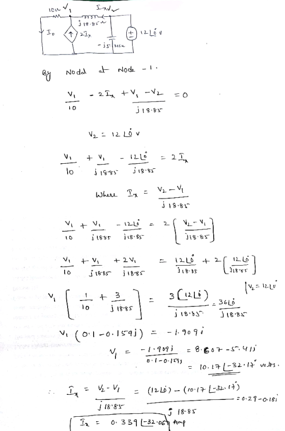
QUESTION 5 Consider the circuit below 10Ω J18.85 Ω 21 l What is l-o in phasor...
About Exercise 8.4.9 In the phasor-domain circuit shown below. I-2/0° A, R1 -20 Ω, R2 1...
 About Exercise 8.4.9 In the phasor-domain circuit shown below. I-2/0° A, R1 -20 Ω, R2 1 Ω. R3 5 Ω.ZLI-JD Ω, ZL2-125 Ω, and R2 L a R3 Load L21 Determine S of the load.
4. (10.6) Find the output voltage (as a phasor) in the circuit below. j1 Ω 2Ω...
 4. (10.6) Find the output voltage (as a phasor) in the circuit below. j1 Ω 2Ω W 2020° 192 5/20 5. (10.42) Find the currents and voltages (as phasors) in the circuit below containing an ideal transformer. WW th ot 20 7602 20200 & 10 6. (10.43) Find the voltage (as phasor) in the circuit below containing an ideal transformer. 2:1 2:1 rün 402 W W of 22 2020 -120 lllll j622 lo 7. If Li - 30 mH, L2...
explain clearly and step by step using to study for final exam. will rate tthanks Problem 1: Consider the electrical circuit below and assume R1 = 12Ω, 10Ω, R3-9 Ω, R4-8 Ω, i,-3A, and v.-2 V. Using,...
 explain clearly and step by step using to study for final exam.
will rate tthanks
Problem 1: Consider the electrical circuit below and assume R1 = 12Ω, 10Ω, R3-9 Ω, R4-8 Ω, i,-3A, and v.-2 V. Using, Node-Voltage method, please, find the voltages vi, U2, v3 and the current i depicted in the figure. R1 Vs 1V2 VI RA releience Node .
Problem 1: Consider the electrical circuit below and assume R1 = 12Ω, 10Ω, R3-9 Ω, R4-8 Ω, i,-3A,...
explain clearly and step by step using to study for final exam.
will rate tthanks
Problem 1: Consider the electrical circuit below and assume R1 = 12Ω, 10Ω, R3-9 Ω, R4-8 Ω, i,-3A, and v.-2 V. Using, Node-Voltage method, please, find the voltages vi, U2, v3 and the current i depicted in the figure. R1 Vs 1V2 VI RA releience Node .
Problem 1: Consider the electrical circuit below and assume R1 = 12Ω, 10Ω, R3-9 Ω, R4-8 Ω, i,-3A,...
QUESTION 1 From problem 8.1 (a): For the circuit shown below, find i(o) 10Ω 4Ω 12...
 QUESTION 1 From problem 8.1 (a): For the circuit shown below, find i(o) 10Ω 4Ω 12 V (+ 2 H 04F V 10 A 1.2 A 0.48 A O A
4. Fig. 2 below shows a series R-L circuit: VA Fig. 1 (a) Suppose the phasor...
 4. Fig. 2 below shows a series R-L circuit: VA Fig. 1 (a) Suppose the phasor Kas -12020-v at f= 60 Hz. A = 100 Ω, and L= 0.5 H. Find in the following order: (b) Now, write the expressions for current resistor voltage Kalf), and inductor voltage ws in the form (V or Alsiniot) where the represent voltage, current, or angle in degrees. Remember to multiply ms magnitudes by 1.414 to obtain peak values.
[10marks] Question 3 The circuit in figure below has reached steady state at t-o. If the...
 [10marks] Question 3 The circuit in figure below has reached steady state at t-o. If the make-before- break switch moves to position b at t- o calculate a. i(t) fortO b. v(t) fort s 0 C. p(t) for tso 10Ω 60 Ω 40 2 2.5 H 10marks
Consider the below circuit and suppose ω = 500 rad/sec. What is the equivalent ADMITTANCE with...
 Consider the below circuit and suppose ω = 500 rad/sec. What is the equivalent ADMITTANCE with
respect to terminals a and b?
Question 15 1 pts Consider the below circuit and suppose w = 500rad/ sec. What is the equivalent ADMITTANCE with respect to terminals a and b? 3 uF 2 4 mH Yab = 1/(j15 * 10-4) – 0.51 Yab = 315 * 10-4 + 2jSiemens • Yab = 1/(j15 * 10-4) +2j12 O Yab = 115 * 10-4...
Consider the below circuit and suppose ω = 500 rad/sec. What is the equivalent ADMITTANCE with
respect to terminals a and b?
Question 15 1 pts Consider the below circuit and suppose w = 500rad/ sec. What is the equivalent ADMITTANCE with respect to terminals a and b? 3 uF 2 4 mH Yab = 1/(j15 * 10-4) – 0.51 Yab = 315 * 10-4 + 2jSiemens • Yab = 1/(j15 * 10-4) +2j12 O Yab = 115 * 10-4...
The next three problems refer to the circuit below. The phasor circuit is given; impedances are...
 The next three problems refer to the circuit below. The phasor
circuit is given; impedances are in Ohms and I and Vx represent
phasors I and Vx.
Question 15 (2 points) The next three problems refer to the circuit below. The phasor circuit is given; impedances are in Ohms and I and Vx represent phasors I and Vx- The voltage source is 10/0° V 5 j2 Vx + + 8Vx Which is a correct KVL equation for this circuit? -10...
The next three problems refer to the circuit below. The phasor
circuit is given; impedances are in Ohms and I and Vx represent
phasors I and Vx.
Question 15 (2 points) The next three problems refer to the circuit below. The phasor circuit is given; impedances are in Ohms and I and Vx represent phasors I and Vx- The voltage source is 10/0° V 5 j2 Vx + + 8Vx Which is a correct KVL equation for this circuit? -10...
Q3. In the circuit as shown below, given that R1 = 4 Ω, R2-4 Ω, L...
 Q3. In the circuit as shown below, given that R1 = 4 Ω, R2-4 Ω, L 2 H, and C = 0.5 F, where vs(t) is given by the waveform displayed in the same figure 1 V (a) Determine the s-domain current I(so) at so-0.05 jo.07 (rad/s): IL(So)- Submit Answer Tries 0/3 (b) Determine the t-domain current i(to) at to 4.5 (s): Submit Answer Tries 0/8 Q4. Determine the output voltage in the circuit as shown below, given that Vs-35*u(t)...
Consider the RLC circuit below, with R= 20 12, L = 10 mH, and C =...
 Consider the RLC circuit below, with R= 20 12, L = 10 mH, and C = 5 mF. The voltage source has a voltage amplitude of 26.0 V and an angular frequency of w = 500 rad/s. a) What is the total impedance of the circuit? b) Find the amplitude of the current, and the phase angle, d. c) Draw a phasor diagram of the impedances. Be sure to clearly label Z, R, XL, Xc, and 0. R C E
 About Exercise 8.4.9 In the phasor-domain circuit shown below. I-2/0° A, R1 -20 Ω, R2 1 Ω. R3 5 Ω.ZLI-JD Ω, ZL2-125 Ω, and R2 L a R3 Load L21 Determine S of the load.
 4. (10.6) Find the output voltage (as a phasor) in the circuit below. j1 Ω 2Ω W 2020° 192 5/20 5. (10.42) Find the currents and voltages (as phasors) in the circuit below containing an ideal transformer. WW th ot 20 7602 20200 & 10 6. (10.43) Find the voltage (as phasor) in the circuit below containing an ideal transformer. 2:1 2:1 rün 402 W W of 22 2020 -120 lllll j622 lo 7. If Li - 30 mH, L2...
 explain clearly and step by step using to study for final exam.
will rate tthanks
Problem 1: Consider the electrical circuit below and assume R1 = 12Ω, 10Ω, R3-9 Ω, R4-8 Ω, i,-3A, and v.-2 V. Using, Node-Voltage method, please, find the voltages vi, U2, v3 and the current i depicted in the figure. R1 Vs 1V2 VI RA releience Node .
Problem 1: Consider the electrical circuit below and assume R1 = 12Ω, 10Ω, R3-9 Ω, R4-8 Ω, i,-3A,...
explain clearly and step by step using to study for final exam.
will rate tthanks
Problem 1: Consider the electrical circuit below and assume R1 = 12Ω, 10Ω, R3-9 Ω, R4-8 Ω, i,-3A, and v.-2 V. Using, Node-Voltage method, please, find the voltages vi, U2, v3 and the current i depicted in the figure. R1 Vs 1V2 VI RA releience Node .
Problem 1: Consider the electrical circuit below and assume R1 = 12Ω, 10Ω, R3-9 Ω, R4-8 Ω, i,-3A,...
 QUESTION 1 From problem 8.1 (a): For the circuit shown below, find i(o) 10Ω 4Ω 12 V (+ 2 H 04F V 10 A 1.2 A 0.48 A O A
 4. Fig. 2 below shows a series R-L circuit: VA Fig. 1 (a) Suppose the phasor Kas -12020-v at f= 60 Hz. A = 100 Ω, and L= 0.5 H. Find in the following order: (b) Now, write the expressions for current resistor voltage Kalf), and inductor voltage ws in the form (V or Alsiniot) where the represent voltage, current, or angle in degrees. Remember to multiply ms magnitudes by 1.414 to obtain peak values.
 [10marks] Question 3 The circuit in figure below has reached steady state at t-o. If the make-before- break switch moves to position b at t- o calculate a. i(t) fortO b. v(t) fort s 0 C. p(t) for tso 10Ω 60 Ω 40 2 2.5 H 10marks
 Consider the below circuit and suppose ω = 500 rad/sec. What is the equivalent ADMITTANCE with
respect to terminals a and b?
Question 15 1 pts Consider the below circuit and suppose w = 500rad/ sec. What is the equivalent ADMITTANCE with respect to terminals a and b? 3 uF 2 4 mH Yab = 1/(j15 * 10-4) – 0.51 Yab = 315 * 10-4 + 2jSiemens • Yab = 1/(j15 * 10-4) +2j12 O Yab = 115 * 10-4...
Consider the below circuit and suppose ω = 500 rad/sec. What is the equivalent ADMITTANCE with
respect to terminals a and b?
Question 15 1 pts Consider the below circuit and suppose w = 500rad/ sec. What is the equivalent ADMITTANCE with respect to terminals a and b? 3 uF 2 4 mH Yab = 1/(j15 * 10-4) – 0.51 Yab = 315 * 10-4 + 2jSiemens • Yab = 1/(j15 * 10-4) +2j12 O Yab = 115 * 10-4...
 The next three problems refer to the circuit below. The phasor
circuit is given; impedances are in Ohms and I and Vx represent
phasors I and Vx.
Question 15 (2 points) The next three problems refer to the circuit below. The phasor circuit is given; impedances are in Ohms and I and Vx represent phasors I and Vx- The voltage source is 10/0° V 5 j2 Vx + + 8Vx Which is a correct KVL equation for this circuit? -10...
The next three problems refer to the circuit below. The phasor
circuit is given; impedances are in Ohms and I and Vx represent
phasors I and Vx.
Question 15 (2 points) The next three problems refer to the circuit below. The phasor circuit is given; impedances are in Ohms and I and Vx represent phasors I and Vx- The voltage source is 10/0° V 5 j2 Vx + + 8Vx Which is a correct KVL equation for this circuit? -10...
 Q3. In the circuit as shown below, given that R1 = 4 Ω, R2-4 Ω, L 2 H, and C = 0.5 F, where vs(t) is given by the waveform displayed in the same figure 1 V (a) Determine the s-domain current I(so) at so-0.05 jo.07 (rad/s): IL(So)- Submit Answer Tries 0/3 (b) Determine the t-domain current i(to) at to 4.5 (s): Submit Answer Tries 0/8 Q4. Determine the output voltage in the circuit as shown below, given that Vs-35*u(t)...
 Consider the RLC circuit below, with R= 20 12, L = 10 mH, and C = 5 mF. The voltage source has a voltage amplitude of 26.0 V and an angular frequency of w = 500 rad/s. a) What is the total impedance of the circuit? b) Find the amplitude of the current, and the phase angle, d. c) Draw a phasor diagram of the impedances. Be sure to clearly label Z, R, XL, Xc, and 0. R C E
Most questions answered within 3 hours.
-
Two capacitors connected in parallel produce an equivalent
capacitance of 45.0 μF but when connected in...
asked 3 minutes ago -
The differences between the two sets of dependent data are -1,
2,-,2, 2. Round to the...
asked 20 minutes ago -
A χ2-curve, looking at the relationship between age and hours
spent working at an office per...
asked 51 minutes ago -
The pH of a sample of water from a river is 5.0. A
sample of effluent from...
asked 1 hour ago -
At the beginning of the period, the Fabricating Department
budgeted direct labor of $136,500 and equipment...
asked 2 hours ago -
Please answer all
____ 28. Rent control is usually
justified on the grounds that it protects...
asked 2 hours ago -
PARTS A-D HAVE BEEN ANSWERED. WAS TOLD TO REPOST. ONLY ANSWER
PARTS E and F.
A...
asked 2 hours ago -
2) You are given the task of finding a representation for a
circle in a drawing...
asked 3 hours ago -
STUDY QUESTION: Does use of diet drug fen-phen
(fenfluramine-phentermine) cause valvular heart disease?
HINT: Valvular heart...
asked 3 hours ago -
1. An object weighing 40 N rests on a surface. The coefficient
of friction is 0.35....
asked 4 hours ago -
Investor company owns 35% of investee company voting stock and
accounts for the investment under the...
asked 5 hours ago -
The number of major faults on a randomly chosen 1 km stretch of
highway has a...
asked 6 hours ago