


Homework Answers
1)

 2 to 6 are as shown below.
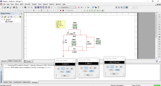
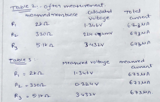
I have done simulation for measuring the voltages resistances and current.
You can observe those measured from above picture.
I'm answering first 6 subparts of your question according to HOMEWORKLIB RULES and also due to time factor. Do post the remaining questions. Will surely answer them. Hope you understand and hope this helps.
Do give a like if you like the answer. It'll encourage me to write more quality answers.
Add Answer to:
Name: ENGT 3050 Fundamentals of Electricity LAB EXERCISE #3 Series and Parallel Circuits Objectives: The objective...
Complete the lab 5 SERIES CIRCUITS VW REFERENCE READING Principles of Electric Circuits: Sectang 81 through...
 Complete the lab 5
SERIES CIRCUITS VW REFERENCE READING Principles of Electric Circuits: Sectang 81 through 6-4. RELATED PROBLEMS FROM PRINCIPLES OF ELECTRIC CIRCUITS Chapter 5, Problems 1 through 26. OBJECTIVE To verify that the total resistance in a series-connected circuit is the sum of the individual resistances. EQUIPMENT dc power supply 0-10 V DMM or VOM Resistors (+5%): 110 2k12 322 3.9 kn 6.1 kn BACKGROUND When resistors are connected in series, the current that will flow is calculated...
Complete the lab 5
SERIES CIRCUITS VW REFERENCE READING Principles of Electric Circuits: Sectang 81 through 6-4. RELATED PROBLEMS FROM PRINCIPLES OF ELECTRIC CIRCUITS Chapter 5, Problems 1 through 26. OBJECTIVE To verify that the total resistance in a series-connected circuit is the sum of the individual resistances. EQUIPMENT dc power supply 0-10 V DMM or VOM Resistors (+5%): 110 2k12 322 3.9 kn 6.1 kn BACKGROUND When resistors are connected in series, the current that will flow is calculated...
ENGR 1181 Lab 3: Circuits Preparation Material Lab 3: Circuits Lab-Pre-lab Assignment Team Seat No. Name...
 ENGR 1181 Lab 3: Circuits Preparation Material Lab 3: Circuits Lab-Pre-lab Assignment Team Seat No. Name This is an individual assignment Solve the five problems below and hand it in at the beginning of the Circuits Lab. Show all your work Problem 1. Ohm's Law For the circuit below, calculate the value of the resistor R which would cause the current of 2.5 mA to flow in the circuit What voltage would you measure across the resistor? Show your calculations....
Course and Section cto EXPERIMENT ac series-Parallel Sinusoidal Circuits OBJECTIVES 1. Measure th...
 Course and Section cto EXPERIMENT ac series-Parallel Sinusoidal Circuits OBJECTIVES 1. Measure the currents of series-parallel R-L and R-C networks using sensing resistors 2. Demonstrate the Pythagorean relationship between the currents of the networks. 3. Measure the phase angles associated with the currents of the networks. 4. Calculate the input impedance of a parallel network using measured values EQUIPMENT REQUIRED Instruments Resistors 1-10-Q, 470-Ω, l-kM (14.W) Inductors 1-10-mH Capacitors 1-0.02-pF I-DMM 1--Oscilloscope 1-Audio oscillator or function generator 1--Frequency counter (if...
ANALYSIS Use your experimental results to analyze the circuit in terms of Kirchhoff net current fow...
 ANALYSIS Use your experimental results to analyze the circuit in terms of Kirchhoff net current fow into and out of each of the four nodes, and determine whetheC s Rules. Consider supported by your data. Determine the net voltage drop around at leaston Sign determine whether or not your data supports the loop rule. (Pay close attosed loops convention.) In adition, verify ir Ohm's law is satisfied for at least three resistors and for the total reji >Q12: Why do...
R1 Vin {R2 13|VRS R4 ob Configure the circuit above in Autodesk Circuits in TinkerCAD. Use...
 R1 Vin {R2 13|VRS R4 ob Configure the circuit above in Autodesk Circuits in TinkerCAD. Use a breadboard and any relevant components/equipment. The parameters for the components in the circuit are: DC supply voltage of 12V, R1 = 3309, R2 = 4700, R3 = 100n and R4 = 2200 a) Measure the voltage across resistor R3 using a multimeter and give the measured voltage b) Measure the current through resistor R3 using a multimeter and give the measured current mA...
How do I calculate the “calculated current flowing through each resistor using Kirchhoffs junction rule and...
 How do I calculate the
“calculated current flowing through each resistor using Kirchhoffs
junction rule and the measured values”? Please show your work.
Thank you!
Old Dominion University Physics 112 & 232 Lab 2. Use the EXTECH Digital M measure the individual resi "orange, black, brown" band Turn on the DMM and turn 2000 Ω position. 2 V 1.5 V Using wire leads with ab and alligator clip on opp banana plug end of a red wi 2) jack, and...
How do I calculate the
“calculated current flowing through each resistor using Kirchhoffs
junction rule and the measured values”? Please show your work.
Thank you!
Old Dominion University Physics 112 & 232 Lab 2. Use the EXTECH Digital M measure the individual resi "orange, black, brown" band Turn on the DMM and turn 2000 Ω position. 2 V 1.5 V Using wire leads with ab and alligator clip on opp banana plug end of a red wi 2) jack, and...
Experiment RESISTANCE IN COMBINATION PURPOSE: To study series, parallel, and series.parallel combinations of resistors. EQUIPMENTThe experiment...
 Experiment RESISTANCE IN COMBINATION PURPOSE: To study series, parallel, and series.parallel combinations of resistors. EQUIPMENTThe experiment board and accompanying bundle of connecting wires. PROCEDURE: 1. Resistors in series: Connect the circuit shown in Fig. 1. Using circuit theory (Ohms Law in conjunction with the predicted procedure for combining resistors in series), calculate the expected current in or through the three resistors in series and the expected voltage across each of the three resistors. After the instructor has approved your connections,...
Solve it and show the work for each circuits 11. Determine the total resistance of the...
 Solve it and show the work for each circuits
11. Determine the total resistance of the circuit illustrated to the right using the reciprocal formula introduced in class R1 2.2k03.3k0 R2 15 V 12. Construct the circuit illustrated to the right and, with the source 13. Use the total resistance to calculate the total circuit current. 14. Connect the source to the circuit and measure the total circuit current. 15. Determine the percent deviation of the resistance and current. 16....
Solve it and show the work for each circuits
11. Determine the total resistance of the circuit illustrated to the right using the reciprocal formula introduced in class R1 2.2k03.3k0 R2 15 V 12. Construct the circuit illustrated to the right and, with the source 13. Use the total resistance to calculate the total circuit current. 14. Connect the source to the circuit and measure the total circuit current. 15. Determine the percent deviation of the resistance and current. 16....
In this Lab you would connect resistors in various combinations then use the multi- meter to...
 In this Lab you would connect resistors in various combinations then use the multi- meter to measure various currents and voltages. I have copied the schematics of the various circuits from the lab and completed portions of the data table with hypothetical (but highly probable) answers. Your task is to complete the data tables and answer the following questions. The value of a resistor can be determined by reading the colored stripes on the resistor. The color codes are given...
Laboratory Measurements Make the circuit 2.1. Measure the voltages and currents and record the measured values...
 Laboratory Measurements Make the circuit 2.1. Measure the voltages and currents and record the measured values in Table 2.1. Make the circuit 2.2. Measure the voltages and currents and record the measured values in Table 2.2. Make the circuit 2.3. Measure the voltages and currents and record the measured values in Table 2.3 Circuit 2.1 R1 A R3 1.2kohm 2.2kohm V2 R2 18V 3.3kohm Fig. 2.1 I2- IR3 Table 2.1VRi Calculated (coded) Measured 1- LR1 IR2 Circuit 2.2 R1 R3...
 Complete the lab 5
SERIES CIRCUITS VW REFERENCE READING Principles of Electric Circuits: Sectang 81 through 6-4. RELATED PROBLEMS FROM PRINCIPLES OF ELECTRIC CIRCUITS Chapter 5, Problems 1 through 26. OBJECTIVE To verify that the total resistance in a series-connected circuit is the sum of the individual resistances. EQUIPMENT dc power supply 0-10 V DMM or VOM Resistors (+5%): 110 2k12 322 3.9 kn 6.1 kn BACKGROUND When resistors are connected in series, the current that will flow is calculated...
Complete the lab 5
SERIES CIRCUITS VW REFERENCE READING Principles of Electric Circuits: Sectang 81 through 6-4. RELATED PROBLEMS FROM PRINCIPLES OF ELECTRIC CIRCUITS Chapter 5, Problems 1 through 26. OBJECTIVE To verify that the total resistance in a series-connected circuit is the sum of the individual resistances. EQUIPMENT dc power supply 0-10 V DMM or VOM Resistors (+5%): 110 2k12 322 3.9 kn 6.1 kn BACKGROUND When resistors are connected in series, the current that will flow is calculated...
 ENGR 1181 Lab 3: Circuits Preparation Material Lab 3: Circuits Lab-Pre-lab Assignment Team Seat No. Name This is an individual assignment Solve the five problems below and hand it in at the beginning of the Circuits Lab. Show all your work Problem 1. Ohm's Law For the circuit below, calculate the value of the resistor R which would cause the current of 2.5 mA to flow in the circuit What voltage would you measure across the resistor? Show your calculations....
 Course and Section cto EXPERIMENT ac series-Parallel Sinusoidal Circuits OBJECTIVES 1. Measure the currents of series-parallel R-L and R-C networks using sensing resistors 2. Demonstrate the Pythagorean relationship between the currents of the networks. 3. Measure the phase angles associated with the currents of the networks. 4. Calculate the input impedance of a parallel network using measured values EQUIPMENT REQUIRED Instruments Resistors 1-10-Q, 470-Ω, l-kM (14.W) Inductors 1-10-mH Capacitors 1-0.02-pF I-DMM 1--Oscilloscope 1-Audio oscillator or function generator 1--Frequency counter (if...
 ANALYSIS Use your experimental results to analyze the circuit in terms of Kirchhoff net current fow into and out of each of the four nodes, and determine whetheC s Rules. Consider supported by your data. Determine the net voltage drop around at leaston Sign determine whether or not your data supports the loop rule. (Pay close attosed loops convention.) In adition, verify ir Ohm's law is satisfied for at least three resistors and for the total reji >Q12: Why do...
 R1 Vin {R2 13|VRS R4 ob Configure the circuit above in Autodesk Circuits in TinkerCAD. Use a breadboard and any relevant components/equipment. The parameters for the components in the circuit are: DC supply voltage of 12V, R1 = 3309, R2 = 4700, R3 = 100n and R4 = 2200 a) Measure the voltage across resistor R3 using a multimeter and give the measured voltage b) Measure the current through resistor R3 using a multimeter and give the measured current mA...
 How do I calculate the
“calculated current flowing through each resistor using Kirchhoffs
junction rule and the measured values”? Please show your work.
Thank you!
Old Dominion University Physics 112 & 232 Lab 2. Use the EXTECH Digital M measure the individual resi "orange, black, brown" band Turn on the DMM and turn 2000 Ω position. 2 V 1.5 V Using wire leads with ab and alligator clip on opp banana plug end of a red wi 2) jack, and...
How do I calculate the
“calculated current flowing through each resistor using Kirchhoffs
junction rule and the measured values”? Please show your work.
Thank you!
Old Dominion University Physics 112 & 232 Lab 2. Use the EXTECH Digital M measure the individual resi "orange, black, brown" band Turn on the DMM and turn 2000 Ω position. 2 V 1.5 V Using wire leads with ab and alligator clip on opp banana plug end of a red wi 2) jack, and...
 Experiment RESISTANCE IN COMBINATION PURPOSE: To study series, parallel, and series.parallel combinations of resistors. EQUIPMENTThe experiment board and accompanying bundle of connecting wires. PROCEDURE: 1. Resistors in series: Connect the circuit shown in Fig. 1. Using circuit theory (Ohms Law in conjunction with the predicted procedure for combining resistors in series), calculate the expected current in or through the three resistors in series and the expected voltage across each of the three resistors. After the instructor has approved your connections,...
 Solve it and show the work for each circuits
11. Determine the total resistance of the circuit illustrated to the right using the reciprocal formula introduced in class R1 2.2k03.3k0 R2 15 V 12. Construct the circuit illustrated to the right and, with the source 13. Use the total resistance to calculate the total circuit current. 14. Connect the source to the circuit and measure the total circuit current. 15. Determine the percent deviation of the resistance and current. 16....
Solve it and show the work for each circuits
11. Determine the total resistance of the circuit illustrated to the right using the reciprocal formula introduced in class R1 2.2k03.3k0 R2 15 V 12. Construct the circuit illustrated to the right and, with the source 13. Use the total resistance to calculate the total circuit current. 14. Connect the source to the circuit and measure the total circuit current. 15. Determine the percent deviation of the resistance and current. 16....
 In this Lab you would connect resistors in various combinations then use the multi- meter to measure various currents and voltages. I have copied the schematics of the various circuits from the lab and completed portions of the data table with hypothetical (but highly probable) answers. Your task is to complete the data tables and answer the following questions. The value of a resistor can be determined by reading the colored stripes on the resistor. The color codes are given...
 Laboratory Measurements Make the circuit 2.1. Measure the voltages and currents and record the measured values in Table 2.1. Make the circuit 2.2. Measure the voltages and currents and record the measured values in Table 2.2. Make the circuit 2.3. Measure the voltages and currents and record the measured values in Table 2.3 Circuit 2.1 R1 A R3 1.2kohm 2.2kohm V2 R2 18V 3.3kohm Fig. 2.1 I2- IR3 Table 2.1VRi Calculated (coded) Measured 1- LR1 IR2 Circuit 2.2 R1 R3...
Most questions answered within 3 hours.
-
1,1-dimethylcyclorohexane reacts with single bromine atom
asked 6 minutes ago -
The completed Lewis structure of CO2 contains a total
of 0,1,2,3,4,5,6,7,8 covalent bonds
and 0,1,2,3,4,5,6,7,8 lone pairs.
NOTE:...
asked 13 minutes ago -
A 0.0510 M solution of an organic acid has an
[H+] of 7.50×10⁻⁴M .
What is...
asked 10 minutes ago -
what is the profit-maximizing output condition that a
monopolistically competitive firm must satisfy? a) price charged...
asked 14 minutes ago -
Consider the set of ordered pairs shown below. Assuming that the
regression equation is y=3.513+0.429x and...
asked 36 minutes ago -
1. (A) Write two
structural (constitutional)
isomers of C4H8F2?
Please show all of
the
asked 38 minutes ago -
Objective: Practice converting a Boolean logic
expression into it’s truth table and to show the implementation...
asked 35 minutes ago -
1) Name the three holes located in the greater wing of the
sphenoid bone in order...
asked 38 minutes ago -
For the following reaction set-up, which type of hydrocarbon
product would form? 1,4-hexadiene + two Cl2...
asked 41 minutes ago -
Consider the following method that is intended to determine if
the double values d1 and d2...
asked 53 minutes ago -
could someone please post clear drawings of the three structures
in the equilibrium mixture of D-glucose...
asked 1 hour ago -
Using the Properties of Order show that 5n5 +
4n4 + 6n3 + 2n2+ n +...
asked 1 hour ago