
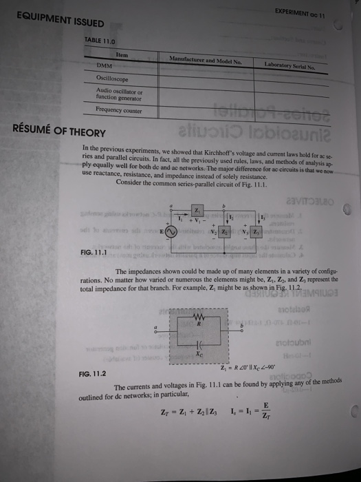


EXPERIMENT ac 11 EQUIPMENT ISSUED TABLE 11.0 Item Manufacturer and Model No. Laboratory Serial No. DMM Oscilloscope Audio oscillator or function generator Frequency counter RÉSUMÉ OF THEORY In the previous experiments, we showed that Kirchhoff's voltage and current laws hold for ac se ries and parallel circuits. In fact, all the previously used rules, laws, and methods of analysis ap- y equally well for both de and ac networks. The major difference for ac circuits is that we no use reactance, resistance, and impedance instead of solely resistance. Consider the common series-parallel circuit of Fig. 11.1. 71 FIG. 11.1 The impedances shown could be made up of many elements in a variety of configu- rations. No matter how varied or numerous the elements might be, Zi, Zz, and Zy represent the total impedance for that branch. For example, Z, might be as shown in Fig. 11.2. HMS notoubni FIG. 11.2 The currents and voltages in Fig. 11.1 can be found by applying any of the methods outlined for de networks; in particular,
SINUSOIDAL CIRCUITS SERIES-PARALLEL 387 and Current Divider Rule) 1, can be determined using Kirchhoff's curvent law Ohm's law provides the voltages Keep in mind that the vollages sand curres are phasot 1,-1,-1 nitude and an associated angle. quantities that have both mag PROCEDURE Part 1 R-L Series-Parallel Network (a) Construct the network of Fig. 11.3. Insert the measured value for cach resistor At the applied frequency, the resistor R, can be ignoeed in comparison with the other elements of the network. Set the source to 8 V (p-p) with the oscilloscope. 470 Ω 10 kHz Black b FIG. 11.3 Use measured resistor values and ignore the effects of R (the internal resistance of the coil). Record the result in Table 11.1. (b) Calculate the magnitude of the input impedance Z of the network at f- 10kHz Calculation:
388 EXPERIMENT oc 11 TABLE 11.1 Measured Calculated (c) Using the results of part 1(b) and Ohm's law, calculate the peak-to-peak value of the source current I,- I, and record in the calculated column of Table 11.1. Calculation: (d) Reverse the leads to the generator (to ensure a common ground between the generator and oscilloscope) and measure the peak-to-peak value of the voltage V, with the oscilloscope. Record in the measured column of Table 11.1 current I, I Record the result in the measured column of Table 11.1. Calculation: Using the measured value for the voltage, calculate the peak-to-peak value of the How does the magnitude of Iucompare with the results of part 1(c)?
L SINUSOIDAL CIRCUITS 389 (e) Determine Z, from the messured value of e and the source following equation Insert the resalt in the measured column of Table 11.1 measured value of Zr compare with the calculated value of part 1by (t) Calculate the peak-to-peak values of the voltage V, V, and V, and insent in the calculated column of Table 11.1 Calculation: of the scope channel to point b and the positive terminal of the channel to point a. Record the readings in the measured column of Table 11.1 (g) Reestablish the network of Fig. 11.3 with R, connected as shown. Measure the peak-to-peak values of V2 and V, with the oscilloscope by connecting the ground terminal What is their relationship? Why?
390 EXPERIMENT ac 11 (h) Using the results of part 1(0, calculate the peak-to-peak valucs of I, I, and 1, and insert in the calculated column of Table 11.1. Calculation: ) Using the result of part 1(g), calculate the peak-to-peak values of the current L and I, and record in the measured column of Table 11.1. Calculation: How do the measured values compare with the calculated values of part 1(0h)? (j) Using the results of parts I(d) and 16), determine whether the following rela- tionship is satisfied using peak-to-peak values: V). Check your method with the instructor and then determine the angle. Be sure to note which leads or lags. Record the results in the top row of Table 11.2 Calculation (lk) Devise a method to measure the phase angle between E and V2
PARALLEL SINUSOIDAL CIRCUITS 391 TABLE 11.2 E and V E and I, E and V (1) Devise a method to measure the phase angle betwcen E and I,-1, Check your method with the instructor and then desermine the angle. Be sure t0 note which leads or la Record the results in the second row of Table 11.2 Calculation: (m) Using the results from the shaded boxes of Table 11.2, calculate the phase angle between E and V1. Record the result in Table 11.2 (n) Using E 8V(p-p)20, draw the phasor diagram of E, V, V, and I,using the above results with the peak-to-peak values.
392 EXPERIMENT ac 11 Is the phasor sum of V, and V, equal to E, as required by Kirchhoff's voltage law? not perform any mathematical calculations but simply note whether the sum of the phasors V Do and V2 on the diagram would result in the source voltage E Part 2 R-C Series-Parallel Network (@) Construct the network of Fig. 11.4. Insert the measured resistor values. Set the source to 8 V (p-p) with the oscilloscope. Red L, 10 kHz 470 Black FIG. 11.4 (b) Calculate the magnitude of the input impedance z, at 1-10 kHz and record the result in Table 11.3. .O715 7747ISS
SERİES-PARALLEL SINUSOIDAL CIRCUITS 393 TABLE 11.3 Calculated 2, Measured 17 (e) Using the result of part 1(b) and Ohm's law, calculate the peak-to-peak value of the source current I, Calculation: I, and record in the calculated columm of Table 11.3. 2 2C (d) Reverse the leads to the generator (to ensure a common ground between the generator and oscilloscope) and measure the peak-to-peak value of the voltage V, with the oscil- loscope. Record the result in the measured column of Table 11.3. Using the measured value for the vollage, calculate the peak-to-peak value of the cur- rent I, = 11, Record the result in the measured column of Table 11.3:0 Calculation
EXPERIMENT ac 11 394 Part 1 I(e How does the magnitude of the measured Ivep) compare to the results of are fla some. e) Determine Z, from the measured value of lep, and the source following equation: Eep Insert the result in the measured column of Table 11.3. Calculation: How does the measured value of Z, compare with the calculated values of part 1(b)? () Calculate the peak-to-peak values of the voltage V, V2, and V, and insert in the calculated column of Table 11.3. Calculation: (g) Reestablish the network of Fig. 11.4 with Ri connected as shown. Measure the peak-to-peak values of V2 and V, with the oscilloscope by connecting the ground terminal of the scope channel to point b and the positive terminal of the channel to point a. Record the readings in the measured column of Table 11.3.
RIES-PARALLEL SINUSOIDAL CIRCun What is their relationship? Why? 395 Ch) Using the result of part 1D.calculate the peak-to-peak values o 1, and I,, and insert in the calculated columa of Table 11.3. Calculation: G) Using the results of part 1(g), calculate the peak-to-peak values of the current I and I, and record in the measured column of Table 11.3. Calculation: How do the measured values compare with the calculated values of part 1(h)? (i) Using the results of parts 1(d) and 10), determine whether the following rela- tionship is satisfied using peak-to-peak values: with your instructor and then determine the angle. Be sure to mote which leads or lags. Record the result in the top row of Table 11.4. (k) Devise a method to measure the phase angle between E and I, Check the method
EXPERIMEN 396 Calculation: TABLE 11.4 D2 Di E and I, E and I I, and I, method with your instructor and then determine the angle. Be sure to note which leads or lags. Recordts result in the second row of Table 11.4 Calculation: 0) Devise a method to measure the phase angle between E and I. Check the metho (m) Devise a method to determine the phase angle between 1, and I, Check the method with your instructor and then determine the angle. Record the result in the last row of Table 11.4. Calculation (n) IfE E 40°, write V, and V2 in phasor form using the results obtained above. Use peak-to-peak values for the magnitudes.
PARALLEL SINUSOIDAL CIRCUITS 397 Vi- (o) Is the following Kirchhofl's w voltage law relationship sanisfied? Use peak to-peak If not, why not? Part 3 R-L-C Series-Parallel Network (a) Construct the network of Fig. 11.5. Insert the measured resistor valoes. Red 10 kHz Black FIG. 11.5 (b) Calculate Z, at a frequency of 10 kHz using the nameplate values of the elements 470 Ω, L-10 mH, C-002 μF) and record in Table 11.5. (Ri-1 kQ, R2
Homework Answers


Add Answer to:
Course and Section cto EXPERIMENT ac series-Parallel Sinusoidal Circuits OBJECTIVES 1. Measure th...
I need a help with my lab, I write all data that get. 355 SERIES SINUSOIDAL...
 I need a help with my lab, I write all data that get.
355 SERIES SINUSOIDAL CIRCU CUITS neeseed 000 10 mH 10 kHz + R E-8V(Pp) V 1 kn Channel 2 Vert: 1 Vidiv Hor: 20 us/div. Channel 1 Vert: 1 Vidiv Hor: 20 us/div. FIG. 9.1 (b) After setting E to 8 V (p-p), determine the peak-to-peak voltage for Ve from chan- nel 2 and record in the top row of Table 9.1 Determine the phase angle 8,...
I need a help with my lab, I write all data that get.
355 SERIES SINUSOIDAL CIRCU CUITS neeseed 000 10 mH 10 kHz + R E-8V(Pp) V 1 kn Channel 2 Vert: 1 Vidiv Hor: 20 us/div. Channel 1 Vert: 1 Vidiv Hor: 20 us/div. FIG. 9.1 (b) After setting E to 8 V (p-p), determine the peak-to-peak voltage for Ve from chan- nel 2 and record in the top row of Table 9.1 Determine the phase angle 8,...
355 SERIES SINUSOIDAL CIRCUITS measared 000 10 mH 10 kHz R E-8V (P-p) Va 1 kn...
 355 SERIES SINUSOIDAL CIRCUITS measared 000 10 mH 10 kHz R E-8V (P-p) Va 1 kn Channel 2 Vert: 1 Vidiv. Har: 20 μεiv . Channel I 1 Vidiv Vert Hoc : 20 μdiv. FIG. 9.1 After setting E to 8 V (p-p), determine the peak-to-peak voltage for Ve from chan- (b) nel 2 and record in the top row of Table 9.1. (c) Determine the phase angle e, between E and Vg using the connections shown in Fig. 9.1...
Name: ENGT 3050 Fundamentals of Electricity LAB EXERCISE #3 Series and Parallel Circuits Objectives: The objective...
 Name: ENGT 3050 Fundamentals of Electricity LAB EXERCISE #3 Series and Parallel Circuits Objectives: The objective of this exercise is to examine Kirchhoff's Voltage and Current Laws. Kirchhoff's Voltage Law (KVL) states, for a closed loop series path the algebraic sum of all the voltages around any closed loop in a circuit is equal to zero. Kirchhoff's Current Law (KCL) states, for a parallel path the total current entering a circuits junction is exactly equal to the total current leaving...
PROCEDU Part 1 Resistance (a) Construct the circuit of Fig. 4.1. Insert the measured values of...
 PROCEDU Part 1 Resistance (a) Construct the circuit of Fig. 4.1. Insert the measured values of the counter if available mined by the ohmmeter section of your multimeter. Hook up the frequeney Red r measured / 100Ω Sensing resistor Red measured 500 Hz Oscilloscope Black Black FIG. 4.1 Caution: Always ensure that the ground of the oscilloscope is connected to the ground of the oscillator. Otherwise a hazardous situation may result (b) Set the voltage across R to 4 V...
would you like please answer all questions in part 3 THEVENIN'S THEOREM AND MAXIMUM POWER TRANSFER...
 would you like please answer all questions in part 3
THEVENIN'S THEOREM AND MAXIMUM POWER TRANSFER 131 Part 3 Maximum Power Transfer (Experimental Approach) (a) Construct the network of Fig. 11.8. Insert the measured value of each resistor R EIOV 95.732 218S2 325 2 . 424e R FIG. 11.8 Eths Vabs 6.8v Rths Resissn (b) The Thevenin equivalent circuit will now be determined for the network to the lel of the terminals a-b without disturbing the structure of the network....
would you like please answer all questions in part 3
THEVENIN'S THEOREM AND MAXIMUM POWER TRANSFER 131 Part 3 Maximum Power Transfer (Experimental Approach) (a) Construct the network of Fig. 11.8. Insert the measured value of each resistor R EIOV 95.732 218S2 325 2 . 424e R FIG. 11.8 Eths Vabs 6.8v Rths Resissn (b) The Thevenin equivalent circuit will now be determined for the network to the lel of the terminals a-b without disturbing the structure of the network....
Bridge Network Part 4 (a) Construct the network of Fig. 14.4. Insert the measured resistor values...
 Bridge Network Part 4 (a) Construct the network of Fig. 14.4. Insert the measured resistor values R3 3.3 k R=3.3 k RImeasured = Vs- R 2.2 k R2 measured - R3 measured E 20 V Is Ra measured =1.2 k = 2.2 k Ra R3 A5 measured FIG. 14.4 (b) Using any one of the three techniques examined in this experiment, calculate the voltage Vs and the current Is. Use the measured resistor values. Record the results in the "Calculated"...
Objectives: To learn transient behavior of series RC circuits To observe of time constant and its...
 Objectives: To learn transient behavior of series RC circuits To observe of time constant and its effect on charging process of capacitor using pulse waveforms Equipment: Oscilloscope Function generator Resistors (1 k) Capacitors (1 uF) Breadboard Pre-Lab Questions A pulse is a voltage or current that changes from one level to the other and back again. If a waveform's high time equals its low time, it is called a square wave. The length of each cycle (one positive peak and...
Experiment RESISTANCE IN COMBINATION PURPOSE: To study series, parallel, and series.parallel combinations of resistors. EQUIPMENTThe experiment...
 Experiment RESISTANCE IN COMBINATION PURPOSE: To study series, parallel, and series.parallel combinations of resistors. EQUIPMENTThe experiment board and accompanying bundle of connecting wires. PROCEDURE: 1. Resistors in series: Connect the circuit shown in Fig. 1. Using circuit theory (Ohms Law in conjunction with the predicted procedure for combining resistors in series), calculate the expected current in or through the three resistors in series and the expected voltage across each of the three resistors. After the instructor has approved your connections,...
TITLE: SERIES PARALLEL CIRCUITSI OBJECTIVE: To verify current, voltage, and resistance relati parallel circuit. ance relationships...
 TITLE: SERIES PARALLEL CIRCUITSI OBJECTIVE: To verify current, voltage, and resistance relati parallel circuit. ance relationships in a series- PRELIMINARY: Before beginning the experiment, each student solution for the circuits of FIG.1 and FIG. 2. The student should solve voltage and current that the experiment asks him to measure. student must submit a detailed Puld solve for every value of EQUIPMENT: Feedback Kit DC Ammeter, AD R = 10002 R = 680 2 Rs = 4702 R. = 8202 R....
Date: Course and Section: Instructor: 4 EXPERIMENT ac R-L-C Components OBJECTIVES 1. Develop skills with the...
 Date: Course and Section: Instructor: 4 EXPERIMENT ac R-L-C Components OBJECTIVES 1. Develop skills with the oscilloscope as a voltage-measuring instrument. 2. Learn how to measure the impedance of an element using a current-sensing resistor 3. Compare the measured and nameplate values of a resistor, inductor, and capacitor EQUIPMENT REQUIRED Resistors 1-100-Ω, 1.2-kM, 3.3-kM (1/4-W) Inductors 2-10-mH Capacitors Instruments 1-DMM 1-Oscilloscope 1-Audio oscillator (or signal generator) 1-Frequency counter (if available)
 I need a help with my lab, I write all data that get.
355 SERIES SINUSOIDAL CIRCU CUITS neeseed 000 10 mH 10 kHz + R E-8V(Pp) V 1 kn Channel 2 Vert: 1 Vidiv Hor: 20 us/div. Channel 1 Vert: 1 Vidiv Hor: 20 us/div. FIG. 9.1 (b) After setting E to 8 V (p-p), determine the peak-to-peak voltage for Ve from chan- nel 2 and record in the top row of Table 9.1 Determine the phase angle 8,...
I need a help with my lab, I write all data that get.
355 SERIES SINUSOIDAL CIRCU CUITS neeseed 000 10 mH 10 kHz + R E-8V(Pp) V 1 kn Channel 2 Vert: 1 Vidiv Hor: 20 us/div. Channel 1 Vert: 1 Vidiv Hor: 20 us/div. FIG. 9.1 (b) After setting E to 8 V (p-p), determine the peak-to-peak voltage for Ve from chan- nel 2 and record in the top row of Table 9.1 Determine the phase angle 8,...
 355 SERIES SINUSOIDAL CIRCUITS measared 000 10 mH 10 kHz R E-8V (P-p) Va 1 kn Channel 2 Vert: 1 Vidiv. Har: 20 μεiv . Channel I 1 Vidiv Vert Hoc : 20 μdiv. FIG. 9.1 After setting E to 8 V (p-p), determine the peak-to-peak voltage for Ve from chan- (b) nel 2 and record in the top row of Table 9.1. (c) Determine the phase angle e, between E and Vg using the connections shown in Fig. 9.1...
 Name: ENGT 3050 Fundamentals of Electricity LAB EXERCISE #3 Series and Parallel Circuits Objectives: The objective of this exercise is to examine Kirchhoff's Voltage and Current Laws. Kirchhoff's Voltage Law (KVL) states, for a closed loop series path the algebraic sum of all the voltages around any closed loop in a circuit is equal to zero. Kirchhoff's Current Law (KCL) states, for a parallel path the total current entering a circuits junction is exactly equal to the total current leaving...
 PROCEDU Part 1 Resistance (a) Construct the circuit of Fig. 4.1. Insert the measured values of the counter if available mined by the ohmmeter section of your multimeter. Hook up the frequeney Red r measured / 100Ω Sensing resistor Red measured 500 Hz Oscilloscope Black Black FIG. 4.1 Caution: Always ensure that the ground of the oscilloscope is connected to the ground of the oscillator. Otherwise a hazardous situation may result (b) Set the voltage across R to 4 V...
 would you like please answer all questions in part 3
THEVENIN'S THEOREM AND MAXIMUM POWER TRANSFER 131 Part 3 Maximum Power Transfer (Experimental Approach) (a) Construct the network of Fig. 11.8. Insert the measured value of each resistor R EIOV 95.732 218S2 325 2 . 424e R FIG. 11.8 Eths Vabs 6.8v Rths Resissn (b) The Thevenin equivalent circuit will now be determined for the network to the lel of the terminals a-b without disturbing the structure of the network....
would you like please answer all questions in part 3
THEVENIN'S THEOREM AND MAXIMUM POWER TRANSFER 131 Part 3 Maximum Power Transfer (Experimental Approach) (a) Construct the network of Fig. 11.8. Insert the measured value of each resistor R EIOV 95.732 218S2 325 2 . 424e R FIG. 11.8 Eths Vabs 6.8v Rths Resissn (b) The Thevenin equivalent circuit will now be determined for the network to the lel of the terminals a-b without disturbing the structure of the network....
 Bridge Network Part 4 (a) Construct the network of Fig. 14.4. Insert the measured resistor values R3 3.3 k R=3.3 k RImeasured = Vs- R 2.2 k R2 measured - R3 measured E 20 V Is Ra measured =1.2 k = 2.2 k Ra R3 A5 measured FIG. 14.4 (b) Using any one of the three techniques examined in this experiment, calculate the voltage Vs and the current Is. Use the measured resistor values. Record the results in the "Calculated"...
 Objectives: To learn transient behavior of series RC circuits To observe of time constant and its effect on charging process of capacitor using pulse waveforms Equipment: Oscilloscope Function generator Resistors (1 k) Capacitors (1 uF) Breadboard Pre-Lab Questions A pulse is a voltage or current that changes from one level to the other and back again. If a waveform's high time equals its low time, it is called a square wave. The length of each cycle (one positive peak and...
 Experiment RESISTANCE IN COMBINATION PURPOSE: To study series, parallel, and series.parallel combinations of resistors. EQUIPMENTThe experiment board and accompanying bundle of connecting wires. PROCEDURE: 1. Resistors in series: Connect the circuit shown in Fig. 1. Using circuit theory (Ohms Law in conjunction with the predicted procedure for combining resistors in series), calculate the expected current in or through the three resistors in series and the expected voltage across each of the three resistors. After the instructor has approved your connections,...
 TITLE: SERIES PARALLEL CIRCUITSI OBJECTIVE: To verify current, voltage, and resistance relati parallel circuit. ance relationships in a series- PRELIMINARY: Before beginning the experiment, each student solution for the circuits of FIG.1 and FIG. 2. The student should solve voltage and current that the experiment asks him to measure. student must submit a detailed Puld solve for every value of EQUIPMENT: Feedback Kit DC Ammeter, AD R = 10002 R = 680 2 Rs = 4702 R. = 8202 R....
 Date: Course and Section: Instructor: 4 EXPERIMENT ac R-L-C Components OBJECTIVES 1. Develop skills with the oscilloscope as a voltage-measuring instrument. 2. Learn how to measure the impedance of an element using a current-sensing resistor 3. Compare the measured and nameplate values of a resistor, inductor, and capacitor EQUIPMENT REQUIRED Resistors 1-100-Ω, 1.2-kM, 3.3-kM (1/4-W) Inductors 2-10-mH Capacitors Instruments 1-DMM 1-Oscilloscope 1-Audio oscillator (or signal generator) 1-Frequency counter (if available)
Most questions answered within 3 hours.
-
What kind of materials are found in Leviticus? Give a simple
description of this book. Also...
asked 13 minutes ago -
17.1 Energy drink commercials. A study was designed to compare
Red Bull energy drink commercials. Each...
asked 16 minutes ago -
The life that maximizes net present value and shareholder wealth
is known as...
Physical Life
Economic...
asked 40 minutes ago -
You have to write your code in C++ (as a cpp file) and prepare a
docx...
asked 1 hour ago -
Why does the spectrum of bromocresol green changes at different
pHs? What causes the change?
asked 1 hour ago -
Rice Company has a unit selling price of $690, variable costs
per unit of $390, and...
asked 2 hours ago -
The DeVille Company reported pretax accounting
income on its income statement as follows:
2018
$
425,000...
asked 2 hours ago -
Argue for or against the "Three Strikes"laws. Provide a rationale
to support your response.
asked 3 hours ago -
Bargaining Models: what is the "Obsolescing Bargain"?
Bargaining Models: what are the factors that would tend...
asked 4 hours ago -
1. A ball is thrown up into the air.
a) Draw motion diagram and the point-like...
asked 4 hours ago -
1) Because money eliminates the "double coincidence of wants"
problem, the development of money as a...
asked 5 hours ago -
Company AAA produces only one product which other manufacturers
purchase as a component for their final...
asked 7 hours ago