 Please show all the steps and calculations,
thanks
Please show all the steps and calculations,
thanks
Homework Answers
Add Answer to:
Please show all the steps and calculations,
thanks
PROBLEM 1 The rolled-steel beam shown has been...
PROBLEM 6.5 The American Standard rolled-steel beam shown has been reinforced by attaching to it two...
 PROBLEM 6.5 The American Standard rolled-steel beam shown has been reinforced by attaching to it two 16 x. 200 mm plates, using 18-mm-diameter bolts spaced longitudinally every 120 mm. Knowing that the average allowable shearing stress in the bolts is 90 MPa determine the largest permissible vertical shearing force. (see Hint table) -16 mm X 200 mm Part A(mm) d (mm) Ad? (109 mm) (106 mm) S310 X 52 Top plate S310x52 Bot. plate 6650 0 95.3 1 164.86 95.44...
GE206, 2018 Spring Name: 3/28/2018, close book (one summary sheet allowed) 2. The American Standard rolled-steel...
 GE206, 2018 Spring Name: 3/28/2018, close book (one summary sheet allowed) 2. The American Standard rolled-steel beam, 5310 x74, shown has been reinforced by attaching to it two 16 x 200 -mm plates, using 18-mm diameter boits spaced longitudinally every 120 mm Knowing that the average allowable shearing stress in the bolts is 90 MPa, determine the largest permissible vertical shearing force. (50 points 16 x 200 mm 8310X74
Could anyone please help me with Problem #1.1 based on the cross-section given in Problem #6.5?...
 Could anyone please help me
with Problem #1.1 based on the cross-section given in Problem #6.5?
Thank you so much!
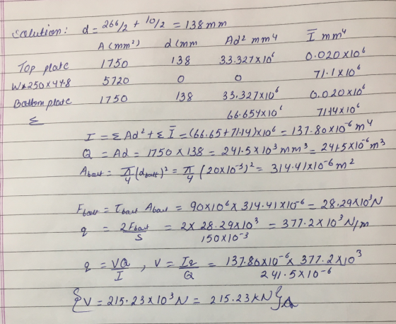
1.1 A simply supported 5-m beam, with the cross section shown in Text Problem 6.5, supports a uniformly distributed load. Determine the maximum required strength per unit length (longitudinal shear flow) at the 12 mm x 175 mm plate-W250x44.8 section bolted connection interface for the beam to develop its maximum moment. Assume the maximum allowable tensile/compressive stress in the steel...
Could anyone please help me
with Problem #1.1 based on the cross-section given in Problem #6.5?
Thank you so much!
1.1 A simply supported 5-m beam, with the cross section shown in Text Problem 6.5, supports a uniformly distributed load. Determine the maximum required strength per unit length (longitudinal shear flow) at the 12 mm x 175 mm plate-W250x44.8 section bolted connection interface for the beam to develop its maximum moment. Assume the maximum allowable tensile/compressive stress in the steel...
Required information A composite beam is made by attaching the timber and steel portions shown with...
 Required information A composite beam is made by attaching the timber and steel portions shown with bolts of 12-mm diameter spaced longitudinally every 200 mm. The modulus of elasticity is 10 GPa for the wood and 200 GPa for the steel. The vertical shear is 4.2 KN - 150 mm 12 mm 12 mm Determine the shearing stress at the center of the cross section (Round the final answers to two decimal places.) (Hint: Both Q and are computed by...
The built-up beam is made of steel as shown in Figure 1. Knowing that modulus of...
 The built-up beam is made of steel as shown in Figure 1. Knowing that modulus of elasticity for the steel is E = 200 GPa 150 mm 20 mm 150 mm 150 mm 10 mm M '10 mm 300 mm А Figure 1 (1) If the allowable tensile and compressive stress for the beam are allow tension = 140 MPa and o = 210 MPa. allow compression respectively, determine the maximum allowable internal moment M that can be applied Determine...
1.51 In the steel structure shown, a 6-mm-diameter pin is used at C and 10-mm-diameter pins...
 1.51 In the steel structure shown, a 6-mm-diameter pin is used at C and 10-mm-diameter pins are used at B and D. The ultimate shearing stress is 150 MPa at all connections, and the ultimate normal stress is 400 MPa in link BD. Knowing that a factor of safety of 3.0 is desired, determine the largest load P that can be applied at A. Note that ink BD is not reinforced around the pin holes Front view 18 mm Side...
I need it to be solved in the next 30 min 4) Bottom of the section...
 I need it to be solved in the next 30 min
4) Bottom of the section (Point A) CASIO Draw the shearing stress distribution Problem 2 (8 marks) The two stec 1 plates are bolted to the wooden beam shown by 30-mm-diameter bolts spaced at 150 mm. Knowing tha for steel and beam wood are 200 and 40 GPa, respectively subjected t 7000 N, and that the moduli of elasticity 1. Draw the transformed section showing dimension (Hint: 1 plate)...
I need it to be solved in the next 30 min
4) Bottom of the section (Point A) CASIO Draw the shearing stress distribution Problem 2 (8 marks) The two stec 1 plates are bolted to the wooden beam shown by 30-mm-diameter bolts spaced at 150 mm. Knowing tha for steel and beam wood are 200 and 40 GPa, respectively subjected t 7000 N, and that the moduli of elasticity 1. Draw the transformed section showing dimension (Hint: 1 plate)...
Problem 6 (15 pts) The beam shown is subjected to a vertical shear force of 42 kips and is fabric...
 Problem 6 (15 pts) The beam shown is subjected to a vertical shear force of 42 kips and is fabricated by fastening the C12 x 25 and S20 x 86 rolled steel members with pairs of 0.5 in. diameter bolts as shown. The allowable shear stress of a bolt is 45 ksi. Determine the maximum spacing. C channel ycg- Iz- Bolt Spacing, MAX
Problem 6 (15 pts) The beam shown is subjected to a vertical shear force of 42 kips...
Problem 6 (15 pts) The beam shown is subjected to a vertical shear force of 42 kips and is fabricated by fastening the C12 x 25 and S20 x 86 rolled steel members with pairs of 0.5 in. diameter bolts as shown. The allowable shear stress of a bolt is 45 ksi. Determine the maximum spacing. C channel ycg- Iz- Bolt Spacing, MAX
Problem 6 (15 pts) The beam shown is subjected to a vertical shear force of 42 kips...
Question 3 For the simply supported steel beam with cross section and loading shown (see Figure...
 Question 3 For the simply supported steel beam with cross section and loading shown (see Figure 3a), knowing that uniformly distributed load w=60 kN/m, Young modulus E = 200 GPa, and yield stress Cyield=200 MPa (in both tension and compression). ул 15 mm w=60 kN/m ... 1 B A 15 mm + 300 mm IC - i 2.5m 1 1 15 mm 7.5m 1 150 mm Figure 3a (a) Check if: the beam is safe with respect to yielding (using...
In the steel structure shown, a 6-mm-diameter pin is used at C and 10-mm-diameter pins are...
 In the steel structure shown, a 6-mm-diameter pin is used at C and 10-mm-diameter pins are used at B and D. The ultimate shearing stress is 159 MPa at all connections, and the ultimate normal stress is 400 MPa in link BD. Knowing that a factor of safety of 3.0 is desired, determine the largest load P that can be applied at A. Note that link BD is not reinforced around the pin holes. (Round the final answer to three...
 PROBLEM 6.5 The American Standard rolled-steel beam shown has been reinforced by attaching to it two 16 x. 200 mm plates, using 18-mm-diameter bolts spaced longitudinally every 120 mm. Knowing that the average allowable shearing stress in the bolts is 90 MPa determine the largest permissible vertical shearing force. (see Hint table) -16 mm X 200 mm Part A(mm) d (mm) Ad? (109 mm) (106 mm) S310 X 52 Top plate S310x52 Bot. plate 6650 0 95.3 1 164.86 95.44...
 GE206, 2018 Spring Name: 3/28/2018, close book (one summary sheet allowed) 2. The American Standard rolled-steel beam, 5310 x74, shown has been reinforced by attaching to it two 16 x 200 -mm plates, using 18-mm diameter boits spaced longitudinally every 120 mm Knowing that the average allowable shearing stress in the bolts is 90 MPa, determine the largest permissible vertical shearing force. (50 points 16 x 200 mm 8310X74
 Could anyone please help me
with Problem #1.1 based on the cross-section given in Problem #6.5?
Thank you so much!
1.1 A simply supported 5-m beam, with the cross section shown in Text Problem 6.5, supports a uniformly distributed load. Determine the maximum required strength per unit length (longitudinal shear flow) at the 12 mm x 175 mm plate-W250x44.8 section bolted connection interface for the beam to develop its maximum moment. Assume the maximum allowable tensile/compressive stress in the steel...
Could anyone please help me
with Problem #1.1 based on the cross-section given in Problem #6.5?
Thank you so much!
1.1 A simply supported 5-m beam, with the cross section shown in Text Problem 6.5, supports a uniformly distributed load. Determine the maximum required strength per unit length (longitudinal shear flow) at the 12 mm x 175 mm plate-W250x44.8 section bolted connection interface for the beam to develop its maximum moment. Assume the maximum allowable tensile/compressive stress in the steel...
 Required information A composite beam is made by attaching the timber and steel portions shown with bolts of 12-mm diameter spaced longitudinally every 200 mm. The modulus of elasticity is 10 GPa for the wood and 200 GPa for the steel. The vertical shear is 4.2 KN - 150 mm 12 mm 12 mm Determine the shearing stress at the center of the cross section (Round the final answers to two decimal places.) (Hint: Both Q and are computed by...
 The built-up beam is made of steel as shown in Figure 1. Knowing that modulus of elasticity for the steel is E = 200 GPa 150 mm 20 mm 150 mm 150 mm 10 mm M '10 mm 300 mm А Figure 1 (1) If the allowable tensile and compressive stress for the beam are allow tension = 140 MPa and o = 210 MPa. allow compression respectively, determine the maximum allowable internal moment M that can be applied Determine...
 1.51 In the steel structure shown, a 6-mm-diameter pin is used at C and 10-mm-diameter pins are used at B and D. The ultimate shearing stress is 150 MPa at all connections, and the ultimate normal stress is 400 MPa in link BD. Knowing that a factor of safety of 3.0 is desired, determine the largest load P that can be applied at A. Note that ink BD is not reinforced around the pin holes Front view 18 mm Side...
 I need it to be solved in the next 30 min
4) Bottom of the section (Point A) CASIO Draw the shearing stress distribution Problem 2 (8 marks) The two stec 1 plates are bolted to the wooden beam shown by 30-mm-diameter bolts spaced at 150 mm. Knowing tha for steel and beam wood are 200 and 40 GPa, respectively subjected t 7000 N, and that the moduli of elasticity 1. Draw the transformed section showing dimension (Hint: 1 plate)...
I need it to be solved in the next 30 min
4) Bottom of the section (Point A) CASIO Draw the shearing stress distribution Problem 2 (8 marks) The two stec 1 plates are bolted to the wooden beam shown by 30-mm-diameter bolts spaced at 150 mm. Knowing tha for steel and beam wood are 200 and 40 GPa, respectively subjected t 7000 N, and that the moduli of elasticity 1. Draw the transformed section showing dimension (Hint: 1 plate)...
 Problem 6 (15 pts) The beam shown is subjected to a vertical shear force of 42 kips and is fabricated by fastening the C12 x 25 and S20 x 86 rolled steel members with pairs of 0.5 in. diameter bolts as shown. The allowable shear stress of a bolt is 45 ksi. Determine the maximum spacing. C channel ycg- Iz- Bolt Spacing, MAX
Problem 6 (15 pts) The beam shown is subjected to a vertical shear force of 42 kips...
Problem 6 (15 pts) The beam shown is subjected to a vertical shear force of 42 kips and is fabricated by fastening the C12 x 25 and S20 x 86 rolled steel members with pairs of 0.5 in. diameter bolts as shown. The allowable shear stress of a bolt is 45 ksi. Determine the maximum spacing. C channel ycg- Iz- Bolt Spacing, MAX
Problem 6 (15 pts) The beam shown is subjected to a vertical shear force of 42 kips...
 Question 3 For the simply supported steel beam with cross section and loading shown (see Figure 3a), knowing that uniformly distributed load w=60 kN/m, Young modulus E = 200 GPa, and yield stress Cyield=200 MPa (in both tension and compression). ул 15 mm w=60 kN/m ... 1 B A 15 mm + 300 mm IC - i 2.5m 1 1 15 mm 7.5m 1 150 mm Figure 3a (a) Check if: the beam is safe with respect to yielding (using...
 In the steel structure shown, a 6-mm-diameter pin is used at C and 10-mm-diameter pins are used at B and D. The ultimate shearing stress is 159 MPa at all connections, and the ultimate normal stress is 400 MPa in link BD. Knowing that a factor of safety of 3.0 is desired, determine the largest load P that can be applied at A. Note that link BD is not reinforced around the pin holes. (Round the final answer to three...
Most questions answered within 3 hours.
-
just another way of saying good target marketing and
understanding customer needs? Why or why not?
asked 30 minutes ago -
Consider the quantum number sets listed below.
What is the name of the smallest element for...
asked 2 hours ago -
In python,write a function nameSet(first, last) that takes a
person's first and last names as input,...
asked 4 hours ago -
How do you think we should value management? Specifically how
might we try to determine MRPL...
asked 4 hours ago -
Suppose the Central Bank of Turkey starts to pay
interest on reserves. Under what circumstances this...
asked 4 hours ago -
For Bergson the concept of Being contains less reality than does
the concept of Becoming. True...
asked 5 hours ago -
What is the hydroxide ion concentration, [OH-], in a solution
with a hydronium ion concentration, [H3O+]...
asked 5 hours ago -
What species is the reducing agent in the following
equation?
Mg(s) + 2HCl (aq) --> MgCl2(aq)...
asked 5 hours ago -
A 50g ice cube is taken out of a freezer at 0 degrees Celsius
and put...
asked 7 hours ago -
How do ratios help you determine trends? What specific
information do managers look at? Is there...
asked 7 hours ago -
A wavelength of 514 nm is used to find an unknown diffraction
grating. If the separation...
asked 7 hours ago -
Use the central limit theorem to find the mean and standard
error of the mean of...
asked 7 hours ago