
Homework Answers


Add Answer to:
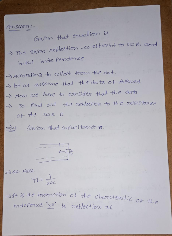
2. Find the reflection coefficient, SWR, and the input impedance at the distance & from the...
Question 4 (a) The input impedance of a lossless air-core transmission line with characteristic impedance Ro. phase constant B and length I terminated in an impedance Z, is given by R,+Z, tan( i....
 Question 4 (a) The input impedance of a lossless air-core transmission line with characteristic impedance Ro. phase constant B and length I terminated in an impedance Z, is given by R,+Z, tan( i. Determine the length of an open circuit 50Ω line required to create a 0.1 nH inductor at a frequency of 10 GHz. (6 marks) ii. Determine the input impedance of the line in part () if the open circuit is changed to a short circuit. (3 marks)...
The input impedance of a 31 - cm - long lossless transmission line of unknown characteristic...
The input impedance of a 31 - cm - long lossless transmission line of unknown characteristic impedance was measured at 1 MHz. With the line terminated in a short circuit, the measurement yielded an input impedance equivalent to an inductor with inductance of 0.064uH, and when the line was open-circuited, the measurement yielded an input impedance equivalent to a capacitor with capacitance of 40uH. Find Zo of the line, the phase velocity, and the relative permittivity of the insulating material.
(f) the distance from the load to the first voltage maximum Use the Smith chart to...
 (f) the distance from the load to the first
voltage maximum
Use the Smith chart to find the following quantities for the transmission line circuit shown in the accompanying figure: (a) The SWR on the line. (b) The reflection coefficient at the load. (c) The load admittance. (d) The input impedance of the line. (e) The distance from the load to the first voltage minimum. — 1= 0.41 OY "z V os = 'z Z1 = 60 + j502
(f) the distance from the load to the first
voltage maximum
Use the Smith chart to find the following quantities for the transmission line circuit shown in the accompanying figure: (a) The SWR on the line. (b) The reflection coefficient at the load. (c) The load admittance. (d) The input impedance of the line. (e) The distance from the load to the first voltage minimum. — 1= 0.41 OY "z V os = 'z Z1 = 60 + j502
6. Design two single-stub matching networks as shown below. Transform the load impedance Z (60 j45) Ω to match an input impedance of Z,-(75+j90)Ω. Assume that both the stub and the transmission line...
 6. Design two single-stub matching networks as shown below. Transform the load impedance Z (60 j45) Ω to match an input impedance of Z,-(75+j90)Ω. Assume that both the stub and the transmission line shown below have a characteristic impedance of Zo-50 Ω. Zot I ZoL.l ZL lm in Open or -) : short circuit , open or short circuit
6. Design two single-stub matching networks as shown below. Transform the load impedance Z (60 j45) Ω to match an input...
6. Design two single-stub matching networks as shown below. Transform the load impedance Z (60 j45) Ω to match an input impedance of Z,-(75+j90)Ω. Assume that both the stub and the transmission line shown below have a characteristic impedance of Zo-50 Ω. Zot I ZoL.l ZL lm in Open or -) : short circuit , open or short circuit
6. Design two single-stub matching networks as shown below. Transform the load impedance Z (60 j45) Ω to match an input...
3, A lossless transmission line of length 1 = 1.57λ and characteristic 17 +j60Ω. impedance Z,...
 3, A lossless transmission line of length 1 = 1.57λ and characteristic 17 +j60Ω. impedance Z, = 50Ω is loaded with an impedance of ZL Compute the following: (a) Reflection coefficient at the load in both rectangular and polar form. (b) SWR, and RL (c) Input impedance at the generator. (d) Reflection coefficient at the input to the transmission line in both rectangular and polar form
A transmission line has an unknown characteristic impedance of Zo. The length L of the transmission...
 A transmission line has an unknown characteristic impedance of Zo. The length L of the transmission line is also unknown. When the transmission line is short circuited (Zi - 0) at one end, the measured input impedance at the other end is Zv Zsc. When the transmission line is open circuited (Zi- oo) at one end, the measured input impedance at the other end is ZiNZoc Find the characteristic impedance Zo of the transmission line.
2.20 Use the Smith chart to find the following quantities for the transmission line circuit shown...
 2.20 Use the Smith chart to find the following quantities for the transmission line circuit shown in the accompanying figure: (a) The SWR on the line. (b) The reflection coefficient at the load. (c) The load admittance. (d) The input impedance of the line (e) The distance from the load to the first voltage minimum. (f) The distance from the load to the first voltage maximum. ZL-60+)50 Ω
Really appreciate any help. Thank you in advance! 1. Use the Smith chart to find the...
Really appreciate any help. Thank you in advance! 1. Use the Smith chart to find the reflection coefficient corresponding to the load impedance ZL =30−j80Ω. 2. Use the Smith chart to find the impedance corresponding to a reflection coefficient of Γ = ◦ 0.5̸ −45. 3. A transmission line is terminated with a load ZL = 80 + j120 Ω. Use the Smith chart to find (a) the load reflection coefficient, (b) the standing wave ratio, (c) the input impedance...
A lossless transmission line with characteristic impedance of 75Ω measures 1.4λ at a certain working frequency....
A lossless transmission line with characteristic impedance of 75Ω measures 1.4λ at a certain working frequency. The line is powered by a generator with negligible impedance and an open circuit voltage of Vg=10∠0° [V]. A load of 50-i50Ω is connected at the end of the line. Find a) The reflection coefficient. b)The stationary wave ratio. c)The input impedance of the line. d)The voltage at the entrance of the line. e)The voltage at the load. f)The average power delivered to the...
lumped element matching network and single stub 2. A transmission line of characteristic impedance Zo 50Q is termina...
 lumped element matching network and single stub
2. A transmission line of characteristic impedance Zo 50Q is terminated with a load impedance Z, 25-j10. Operating frequency is 1GH2 (a) Design impedance matching using L or R lumped element and find the values of L or R. (b) Design impedance matching using single open stub
2. A transmission line of characteristic impedance Zo 50Q is terminated with a load impedance Z, 25-j10. Operating frequency is 1GH2 (a) Design impedance matching using...
lumped element matching network and single stub
2. A transmission line of characteristic impedance Zo 50Q is terminated with a load impedance Z, 25-j10. Operating frequency is 1GH2 (a) Design impedance matching using L or R lumped element and find the values of L or R. (b) Design impedance matching using single open stub
2. A transmission line of characteristic impedance Zo 50Q is terminated with a load impedance Z, 25-j10. Operating frequency is 1GH2 (a) Design impedance matching using...
 Question 4 (a) The input impedance of a lossless air-core transmission line with characteristic impedance Ro. phase constant B and length I terminated in an impedance Z, is given by R,+Z, tan( i. Determine the length of an open circuit 50Ω line required to create a 0.1 nH inductor at a frequency of 10 GHz. (6 marks) ii. Determine the input impedance of the line in part () if the open circuit is changed to a short circuit. (3 marks)...
 (f) the distance from the load to the first
voltage maximum
Use the Smith chart to find the following quantities for the transmission line circuit shown in the accompanying figure: (a) The SWR on the line. (b) The reflection coefficient at the load. (c) The load admittance. (d) The input impedance of the line. (e) The distance from the load to the first voltage minimum. — 1= 0.41 OY "z V os = 'z Z1 = 60 + j502
(f) the distance from the load to the first
voltage maximum
Use the Smith chart to find the following quantities for the transmission line circuit shown in the accompanying figure: (a) The SWR on the line. (b) The reflection coefficient at the load. (c) The load admittance. (d) The input impedance of the line. (e) The distance from the load to the first voltage minimum. — 1= 0.41 OY "z V os = 'z Z1 = 60 + j502
 6. Design two single-stub matching networks as shown below. Transform the load impedance Z (60 j45) Ω to match an input impedance of Z,-(75+j90)Ω. Assume that both the stub and the transmission line shown below have a characteristic impedance of Zo-50 Ω. Zot I ZoL.l ZL lm in Open or -) : short circuit , open or short circuit
6. Design two single-stub matching networks as shown below. Transform the load impedance Z (60 j45) Ω to match an input...
6. Design two single-stub matching networks as shown below. Transform the load impedance Z (60 j45) Ω to match an input impedance of Z,-(75+j90)Ω. Assume that both the stub and the transmission line shown below have a characteristic impedance of Zo-50 Ω. Zot I ZoL.l ZL lm in Open or -) : short circuit , open or short circuit
6. Design two single-stub matching networks as shown below. Transform the load impedance Z (60 j45) Ω to match an input...
 3, A lossless transmission line of length 1 = 1.57λ and characteristic 17 +j60Ω. impedance Z, = 50Ω is loaded with an impedance of ZL Compute the following: (a) Reflection coefficient at the load in both rectangular and polar form. (b) SWR, and RL (c) Input impedance at the generator. (d) Reflection coefficient at the input to the transmission line in both rectangular and polar form
 A transmission line has an unknown characteristic impedance of Zo. The length L of the transmission line is also unknown. When the transmission line is short circuited (Zi - 0) at one end, the measured input impedance at the other end is Zv Zsc. When the transmission line is open circuited (Zi- oo) at one end, the measured input impedance at the other end is ZiNZoc Find the characteristic impedance Zo of the transmission line.
 2.20 Use the Smith chart to find the following quantities for the transmission line circuit shown in the accompanying figure: (a) The SWR on the line. (b) The reflection coefficient at the load. (c) The load admittance. (d) The input impedance of the line (e) The distance from the load to the first voltage minimum. (f) The distance from the load to the first voltage maximum. ZL-60+)50 Ω
 lumped element matching network and single stub
2. A transmission line of characteristic impedance Zo 50Q is terminated with a load impedance Z, 25-j10. Operating frequency is 1GH2 (a) Design impedance matching using L or R lumped element and find the values of L or R. (b) Design impedance matching using single open stub
2. A transmission line of characteristic impedance Zo 50Q is terminated with a load impedance Z, 25-j10. Operating frequency is 1GH2 (a) Design impedance matching using...
lumped element matching network and single stub
2. A transmission line of characteristic impedance Zo 50Q is terminated with a load impedance Z, 25-j10. Operating frequency is 1GH2 (a) Design impedance matching using L or R lumped element and find the values of L or R. (b) Design impedance matching using single open stub
2. A transmission line of characteristic impedance Zo 50Q is terminated with a load impedance Z, 25-j10. Operating frequency is 1GH2 (a) Design impedance matching using...
Most questions answered within 3 hours.
-
The free energy change for the following reaction at 25 °C, when
[Sn2+] = 1.17 M...
asked 1 hour ago -
An MNE is this kind of industry when competition in one country
is essentially independent of...
asked 3 hours ago -
. For this set of questions, determine what
proportion of a normal distribution is located betweeneach...
asked 3 hours ago -
A college student is employed as a door-to-door newspaper
salesman. Historical data suggests that the student...
asked 4 hours ago -
MATLAB HW 11 problem using Switch Case and Input commands
Write a script file that calculates...
asked 4 hours ago -
Considering gravitational time dilation, calculate the time that
passes in Earth’s surface while 1 hour passes...
asked 5 hours ago -
Minitab Problem: Take the Lake Hume June rainfall data and find
use the processes outlined in...
asked 6 hours ago -
X Company is trying to decide whether to continue using old
equipment to make Product A...
asked 6 hours ago -
IN PYTHON ONLY !! Program 2: Re-work
program #5 (WeeklyHours) from the previous assignment such that...
asked 6 hours ago -
The average length of time between arrivals at a turnpike
toll-booth is 26 seconds. What is...
asked 8 hours ago -
(a) A piston at 6.1 atm contains a gas that occupies a volume of
3.5 L....
asked 9 hours ago -
Please answer true or false. Words
cannot be changed or added in to make it true...
asked 9 hours ago