
Homework Answers
Add Answer to:
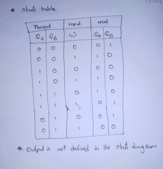
please show your work.
Fill in the state table for the following state diagram. Clearly label...
please show your work Complete the following state table. Note that the flip-flops are not all...
 please show your work
Complete the following state table. Note that the flip-flops are not all of the same type. Present FFin Next QA QB Qc JAKA TB TB Dc QA QB Qc 0 0 0 Ох 1 0 0 0 1 1x 0 1 0 1 0 1x 1 0 0 1 1 Ох 0 1 1 0 0 x1 0 1 1 0 1 х0 1 0 1 1 0 x0 0 1 1 1 1 x1 1...
please show your work
Complete the following state table. Note that the flip-flops are not all of the same type. Present FFin Next QA QB Qc JAKA TB TB Dc QA QB Qc 0 0 0 Ох 1 0 0 0 1 1x 0 1 0 1 0 1x 1 0 0 1 1 Ох 0 1 1 0 0 x1 0 1 1 0 1 х0 1 0 1 1 0 x0 0 1 1 1 1 x1 1...
please show your work Complete the following state table. Note that the flip-flops are not all...
 please show your work
Complete the following state table. Note that the flip-flops are not all of the same type. Present FFin Next QA QB Qc JAKA DB QA Qв Qс 0 о 0 0 0 0 0 0 1 1 1 o 1 0 0 0 0 0 1 1 1 1 0 1 0 0 1 10 10 1 0 0 0 1 1 0 0 1 1 1 1 1 1 10
please show your work
Complete the following state table. Note that the flip-flops are not all of the same type. Present FFin Next QA QB Qc JAKA DB QA Qв Qс 0 о 0 0 0 0 0 0 1 1 1 o 1 0 0 0 0 0 1 1 1 1 0 1 0 0 1 10 10 1 0 0 0 1 1 0 0 1 1 1 1 1 1 10
SEQUENCE is 101 In Lab Procedure 1. Draw the state diagram of the state machine below...
 SEQUENCE is 101
In Lab Procedure
1. Draw the state diagram of the state machine below and show it
to the lab instructor.
2. Fill the state table.
3. Assign State numbers
4. Find simplified Expressions (State Equations) for the
flip-flops
5. Draw the circuit diagram using NAND GATES ONLY for the state
machine
STATE DIAGRAM::
STATE TABLE::
State Table Next State Qc Y DA DB Dc Present State QA Qв 0 0 0 0 0 0 0 0 0...
SEQUENCE is 101
In Lab Procedure
1. Draw the state diagram of the state machine below and show it
to the lab instructor.
2. Fill the state table.
3. Assign State numbers
4. Find simplified Expressions (State Equations) for the
flip-flops
5. Draw the circuit diagram using NAND GATES ONLY for the state
machine
STATE DIAGRAM::
STATE TABLE::
State Table Next State Qc Y DA DB Dc Present State QA Qв 0 0 0 0 0 0 0 0 0...
Not just fill the next states with 0 and 1. Please show and explain how to...
 Not just fill the next states with 0 and 1. Please show and
explain how to get to the next state encoder from the diagram.
Thanks!
12. (a) (8 points) Given the state diagram below, create a truth table for the next state encoder. Start AB 01 AB (b) (6 points) Use the truth table you built to produce SOP logic expressions for the two state variables SiSo 00 01 11 10 S1So 00 01 11 10 N, AB 01...
Not just fill the next states with 0 and 1. Please show and
explain how to get to the next state encoder from the diagram.
Thanks!
12. (a) (8 points) Given the state diagram below, create a truth table for the next state encoder. Start AB 01 AB (b) (6 points) Use the truth table you built to produce SOP logic expressions for the two state variables SiSo 00 01 11 10 S1So 00 01 11 10 N, AB 01...
show work plz Consider the following finite state diagram. State 1 Output=1 State 0 Output=0 State...
 show work plz
Consider the following finite state diagram. State 1 Output=1 State 0 Output=0 State 2 Output=1 State 3 Output=0 The diagram has 4 states, 1 external input / (in additional to the CLK input), and 1 output bit Y. State 0 is represented by memory bits Qi Qo=00, State 1 is represented by memory bits Q.Qo=01, State 2 is represented by memory bits Q.Qo = 10, and State 3 is represented by memory bits Q.Qo = 11. The...
show work plz
Consider the following finite state diagram. State 1 Output=1 State 0 Output=0 State 2 Output=1 State 3 Output=0 The diagram has 4 states, 1 external input / (in additional to the CLK input), and 1 output bit Y. State 0 is represented by memory bits Qi Qo=00, State 1 is represented by memory bits Q.Qo=01, State 2 is represented by memory bits Q.Qo = 10, and State 3 is represented by memory bits Q.Qo = 11. The...
* Question Completion Status: Question 2 35 points Save Answe Fill the state/excitation table for the...
 * Question Completion Status: Question 2 35 points Save Answe Fill the state/excitation table for the sequential circuit specified by the state diagram of Figure 1 assuming that T-type flip-flops are used. (Write 0 or 1 in each cell) 00 10 01 11 Figure 1 Present State Input Next State Flip-Flop Inputs A(t) B(t) A(t+1) B(t+1) TA TB 0 0 0 0 0 0 1 0 0 1 1 1 0 0 1 0 1 1 1 0 1 1
Using J-K, D, T and D flip- flops in the following order as seen in the table; fill out the next state table that only follows the cycles of the state diagram cycle seen above. After this is done dra...
 Using J-K, D, T and D flip- flops in the following order as seen
in the table; fill out the next state table that only follows the
cycles of the state diagram cycle seen above. After this is done
draw the proper logic circuit to run it in a simulator to see that
it is working properly and the tables where filled in the proper
way.
IT IS SUPPOSE TO STOP ONCE IT REACHES 0000. IT ONLY RUNS THE
CYCLE...
Using J-K, D, T and D flip- flops in the following order as seen
in the table; fill out the next state table that only follows the
cycles of the state diagram cycle seen above. After this is done
draw the proper logic circuit to run it in a simulator to see that
it is working properly and the tables where filled in the proper
way.
IT IS SUPPOSE TO STOP ONCE IT REACHES 0000. IT ONLY RUNS THE
CYCLE...
Consider the following state diagram, which items on the state table is correct for the switch...
 Consider the following state diagram, which items on the state table is correct for the switch between states and output values. (Fig. 30) So S7 Food S Sz SS l%0 S2 Sc 70 %0 So Next state Z2Z1 Current state A. B. C. D. SO S1 S2 S3 X=0 S3 S4 S3 S3 X=1 X=0 S1 00 S1 01 10 S4 00 Fig. 30 X=1 00 00 10 00 S2 A. Line A on the table Line B on the...
*State diagrams are the same just had to upload it in two pictures, sorry. The state...
 *State diagrams are the same just had to upload it in two
pictures, sorry.
The state diagram below has two inputs, a and b, and two outputs, x and y. It also has 3 states: 00, 01, and 10. Please complete the truth table for the combinational logic that implements the behavior of the state diagram. NOTES: 1. The state 01 maps to rows where s1-0 and so = 1 (the next state bits, ni and no, follow the same...
*State diagrams are the same just had to upload it in two
pictures, sorry.
The state diagram below has two inputs, a and b, and two outputs, x and y. It also has 3 states: 00, 01, and 10. Please complete the truth table for the combinational logic that implements the behavior of the state diagram. NOTES: 1. The state 01 maps to rows where s1-0 and so = 1 (the next state bits, ni and no, follow the same...
 please show your work
Complete the following state table. Note that the flip-flops are not all of the same type. Present FFin Next QA QB Qc JAKA TB TB Dc QA QB Qc 0 0 0 Ох 1 0 0 0 1 1x 0 1 0 1 0 1x 1 0 0 1 1 Ох 0 1 1 0 0 x1 0 1 1 0 1 х0 1 0 1 1 0 x0 0 1 1 1 1 x1 1...
please show your work
Complete the following state table. Note that the flip-flops are not all of the same type. Present FFin Next QA QB Qc JAKA TB TB Dc QA QB Qc 0 0 0 Ох 1 0 0 0 1 1x 0 1 0 1 0 1x 1 0 0 1 1 Ох 0 1 1 0 0 x1 0 1 1 0 1 х0 1 0 1 1 0 x0 0 1 1 1 1 x1 1...
 please show your work
Complete the following state table. Note that the flip-flops are not all of the same type. Present FFin Next QA QB Qc JAKA DB QA Qв Qс 0 о 0 0 0 0 0 0 1 1 1 o 1 0 0 0 0 0 1 1 1 1 0 1 0 0 1 10 10 1 0 0 0 1 1 0 0 1 1 1 1 1 1 10
please show your work
Complete the following state table. Note that the flip-flops are not all of the same type. Present FFin Next QA QB Qc JAKA DB QA Qв Qс 0 о 0 0 0 0 0 0 1 1 1 o 1 0 0 0 0 0 1 1 1 1 0 1 0 0 1 10 10 1 0 0 0 1 1 0 0 1 1 1 1 1 1 10
 SEQUENCE is 101
In Lab Procedure
1. Draw the state diagram of the state machine below and show it
to the lab instructor.
2. Fill the state table.
3. Assign State numbers
4. Find simplified Expressions (State Equations) for the
flip-flops
5. Draw the circuit diagram using NAND GATES ONLY for the state
machine
STATE DIAGRAM::
STATE TABLE::
State Table Next State Qc Y DA DB Dc Present State QA Qв 0 0 0 0 0 0 0 0 0...
SEQUENCE is 101
In Lab Procedure
1. Draw the state diagram of the state machine below and show it
to the lab instructor.
2. Fill the state table.
3. Assign State numbers
4. Find simplified Expressions (State Equations) for the
flip-flops
5. Draw the circuit diagram using NAND GATES ONLY for the state
machine
STATE DIAGRAM::
STATE TABLE::
State Table Next State Qc Y DA DB Dc Present State QA Qв 0 0 0 0 0 0 0 0 0...
 Not just fill the next states with 0 and 1. Please show and
explain how to get to the next state encoder from the diagram.
Thanks!
12. (a) (8 points) Given the state diagram below, create a truth table for the next state encoder. Start AB 01 AB (b) (6 points) Use the truth table you built to produce SOP logic expressions for the two state variables SiSo 00 01 11 10 S1So 00 01 11 10 N, AB 01...
Not just fill the next states with 0 and 1. Please show and
explain how to get to the next state encoder from the diagram.
Thanks!
12. (a) (8 points) Given the state diagram below, create a truth table for the next state encoder. Start AB 01 AB (b) (6 points) Use the truth table you built to produce SOP logic expressions for the two state variables SiSo 00 01 11 10 S1So 00 01 11 10 N, AB 01...
 show work plz
Consider the following finite state diagram. State 1 Output=1 State 0 Output=0 State 2 Output=1 State 3 Output=0 The diagram has 4 states, 1 external input / (in additional to the CLK input), and 1 output bit Y. State 0 is represented by memory bits Qi Qo=00, State 1 is represented by memory bits Q.Qo=01, State 2 is represented by memory bits Q.Qo = 10, and State 3 is represented by memory bits Q.Qo = 11. The...
show work plz
Consider the following finite state diagram. State 1 Output=1 State 0 Output=0 State 2 Output=1 State 3 Output=0 The diagram has 4 states, 1 external input / (in additional to the CLK input), and 1 output bit Y. State 0 is represented by memory bits Qi Qo=00, State 1 is represented by memory bits Q.Qo=01, State 2 is represented by memory bits Q.Qo = 10, and State 3 is represented by memory bits Q.Qo = 11. The...
 * Question Completion Status: Question 2 35 points Save Answe Fill the state/excitation table for the sequential circuit specified by the state diagram of Figure 1 assuming that T-type flip-flops are used. (Write 0 or 1 in each cell) 00 10 01 11 Figure 1 Present State Input Next State Flip-Flop Inputs A(t) B(t) A(t+1) B(t+1) TA TB 0 0 0 0 0 0 1 0 0 1 1 1 0 0 1 0 1 1 1 0 1 1
 Using J-K, D, T and D flip- flops in the following order as seen
in the table; fill out the next state table that only follows the
cycles of the state diagram cycle seen above. After this is done
draw the proper logic circuit to run it in a simulator to see that
it is working properly and the tables where filled in the proper
way.
IT IS SUPPOSE TO STOP ONCE IT REACHES 0000. IT ONLY RUNS THE
CYCLE...
Using J-K, D, T and D flip- flops in the following order as seen
in the table; fill out the next state table that only follows the
cycles of the state diagram cycle seen above. After this is done
draw the proper logic circuit to run it in a simulator to see that
it is working properly and the tables where filled in the proper
way.
IT IS SUPPOSE TO STOP ONCE IT REACHES 0000. IT ONLY RUNS THE
CYCLE...
 Consider the following state diagram, which items on the state table is correct for the switch between states and output values. (Fig. 30) So S7 Food S Sz SS l%0 S2 Sc 70 %0 So Next state Z2Z1 Current state A. B. C. D. SO S1 S2 S3 X=0 S3 S4 S3 S3 X=1 X=0 S1 00 S1 01 10 S4 00 Fig. 30 X=1 00 00 10 00 S2 A. Line A on the table Line B on the...
 *State diagrams are the same just had to upload it in two
pictures, sorry.
The state diagram below has two inputs, a and b, and two outputs, x and y. It also has 3 states: 00, 01, and 10. Please complete the truth table for the combinational logic that implements the behavior of the state diagram. NOTES: 1. The state 01 maps to rows where s1-0 and so = 1 (the next state bits, ni and no, follow the same...
*State diagrams are the same just had to upload it in two
pictures, sorry.
The state diagram below has two inputs, a and b, and two outputs, x and y. It also has 3 states: 00, 01, and 10. Please complete the truth table for the combinational logic that implements the behavior of the state diagram. NOTES: 1. The state 01 maps to rows where s1-0 and so = 1 (the next state bits, ni and no, follow the same...
Most questions answered within 3 hours.
-
Calculate the pH of each of the following solutions.
0.50 M HBr
3.1×10⁻⁴ M KOH
4.2×10⁻⁵...
asked 1 hour ago -
For the year ended December 31, Depot Max’s cost of merchandise
sold was $85,600. Inventory at the...
asked 1 hour ago -
Week 10 - Professional Memo Assignment
Professional Memo Assignment
Your mission for this week, should you...
asked 1 hour ago -
Write a Python program that stores the data for each
player on the team, and it...
asked 1 hour ago -
In
the last 3 months, mike never knows when he is going to get his
allowance...
asked 2 hours ago -
Is Ca(OH)2 a Bronsted base, Lewis base, or both? Why?
asked 2 hours ago -
1A- Why don’t voters complain about U.S. tariffs on imported
sugar?
Because sugar is only a...
asked 2 hours ago -
Cash Payback Period
Primera Banco is evaluating two capital investment proposals for
a drive-up ATM kiosk,...
asked 2 hours ago -
Create a button in Swift (Xcode) that will create a charge,
create a charge using Stripe's...
asked 2 hours ago -
The reaction rate of CO and NO2 in the reaction
CO(g) + NO2(g) → CO2(g) +...
asked 2 hours ago -
Imagine that a chemist puts 6.40 mol each of
C3H8 and O2 in a 1.00-L container...
asked 2 hours ago -
How much money should be invested today in order to have $8340
at the end of...
asked 2 hours ago