
Homework Answers


 SF
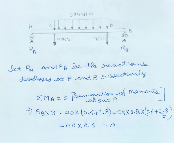
Diagram is constant between A&C and D&B and linearly
varying between C&D.
SF
Diagram is constant between A&C and D&B and linearly
varying between C&D.
BM Diagram is linearly varying between A&C and D&B and parabolically varying between C&D.
Add Answer to:
Problem 4. (65 points). For the beam shown, calculate the Reactions at A and B, and...
Problem 4. (65 points). For the beam shown, calculate the Reactions at A and B, and...
 Problem 4. (65 points). For the beam shown, calculate the Reactions at A and B, and then draw the Shear and Bending-Moment diagrams. Consider the loading P= 29 kN/m. P с D А B 40 KN 40 KN 0.6 m 1.8 m 0.6 m
Problem 4. (65 points). For the beam shown, calculate the Reactions at A and B, and...
 Problem 4. (65 points). For the beam shown, calculate the Reactions at A and B, and then draw the Shear and Bending-Moment diagrams. Consider the loading P= 29 kN/m. Р C D А B 40 KN 40 KN toom 0.6 m 1.8 m
For the beam shown, calculate the Reactions at A and B, and then draw the Shear...
 For the beam shown, calculate the Reactions at A and B, and then draw the Shear and Bending Moment diagrams. Consider the loading P=29 kN/m. p D А B 40 KN 40 KN 0.6 m 1.8 m 0.6 m
For the beam shown, calculate the reactions at A and B, and then draw the shear...
 For the beam shown, calculate the reactions at A and B, and then
draw the shear and Bending-Moment diagrams. Consider the loading P=
31 kN/m.
Р с D B 40 KN 40 KN 0.6 m 1.8 m 0,6 m
For the beam shown, calculate the reactions at A and B, and then
draw the shear and Bending-Moment diagrams. Consider the loading P=
31 kN/m.
Р с D B 40 KN 40 KN 0.6 m 1.8 m 0,6 m
4. For the beam and loading shown, draw the shear force and bending moment diagrams and...
 4. For the beam and loading shown, draw the shear force and bending moment diagrams and determine the maximum bending and shear force and their locations. 20 KN 40 KN B D 250 mm |--2.5 m- 3m-4-2 m 80 mm 5. For the beam and loading shown, draw the shear force and bending moment diagrams and determine the maximum bending and shear force and their locations. 50 KN
For the beam and loading shown (a) Determine the reactions at A. (b) Draw the shear...
 For the beam and loading shown (a) Determine the reactions at A. (b) Draw the shear and bending moment diagrams for the beam. 2 kN А c B 2 m 2 m 1 kN
A cantilever beam supports the applied loads and moments as shown. (a) Calculate the support reactions....
 A cantilever beam supports the applied loads and moments as shown. (a) Calculate the support reactions. (b) Use the graphical method to construct the shear-force and bending moment diagrams for the beam. Also label the values of shear-force and bending=moment at all key points. 30 kN/m 25 kN 12 kN/m 80 kN.m х A В C D E F 1 m 3 m 1 m 1 m 1 m
For the beam and loading shown, a) find the reactions at A and B b) draw...
 For the beam and loading shown, a) find the reactions at A and B b) draw the shear and bending moment diagrams. Show all the values on both graphs. c) determine the absolute maximum value for the bending moment and its location. NOTE: Show all your work. NOTE: If you need to upload two separate pages, upload the second page to the drop box I have 40 kN/m 20 KN 100 kN.m 8 m
2. For the beam and loading shown in the following figure: (a) find all the reaction...
 2. For the beam and loading shown in the following figure: (a) find all the reaction forces, (b) draw the shear and bending moment diagrams and (c) determine the maximum absolute value of the shear and the bending moment. 25 kN m 40 kN 401N 0.61 1.S 0.6 m
For the beam and loading shown in Figure A2: - a. Determine the support reactions b....
 For the beam and loading shown in Figure A2: - a. Determine the support reactions b. Draw the shear and bending moment diagrams c. Determine the maximum absolute value of shear force and bending moment P= 100 N P= 140 N w = 30 N/m A B 4 m 7 m 10 m 3 Figure A2.
 Problem 4. (65 points). For the beam shown, calculate the Reactions at A and B, and then draw the Shear and Bending-Moment diagrams. Consider the loading P= 29 kN/m. P с D А B 40 KN 40 KN 0.6 m 1.8 m 0.6 m
 Problem 4. (65 points). For the beam shown, calculate the Reactions at A and B, and then draw the Shear and Bending-Moment diagrams. Consider the loading P= 29 kN/m. Р C D А B 40 KN 40 KN toom 0.6 m 1.8 m
 For the beam shown, calculate the Reactions at A and B, and then draw the Shear and Bending Moment diagrams. Consider the loading P=29 kN/m. p D А B 40 KN 40 KN 0.6 m 1.8 m 0.6 m
 For the beam shown, calculate the reactions at A and B, and then
draw the shear and Bending-Moment diagrams. Consider the loading P=
31 kN/m.
Р с D B 40 KN 40 KN 0.6 m 1.8 m 0,6 m
For the beam shown, calculate the reactions at A and B, and then
draw the shear and Bending-Moment diagrams. Consider the loading P=
31 kN/m.
Р с D B 40 KN 40 KN 0.6 m 1.8 m 0,6 m
 4. For the beam and loading shown, draw the shear force and bending moment diagrams and determine the maximum bending and shear force and their locations. 20 KN 40 KN B D 250 mm |--2.5 m- 3m-4-2 m 80 mm 5. For the beam and loading shown, draw the shear force and bending moment diagrams and determine the maximum bending and shear force and their locations. 50 KN
 For the beam and loading shown (a) Determine the reactions at A. (b) Draw the shear and bending moment diagrams for the beam. 2 kN А c B 2 m 2 m 1 kN
 A cantilever beam supports the applied loads and moments as shown. (a) Calculate the support reactions. (b) Use the graphical method to construct the shear-force and bending moment diagrams for the beam. Also label the values of shear-force and bending=moment at all key points. 30 kN/m 25 kN 12 kN/m 80 kN.m х A В C D E F 1 m 3 m 1 m 1 m 1 m
 For the beam and loading shown, a) find the reactions at A and B b) draw the shear and bending moment diagrams. Show all the values on both graphs. c) determine the absolute maximum value for the bending moment and its location. NOTE: Show all your work. NOTE: If you need to upload two separate pages, upload the second page to the drop box I have 40 kN/m 20 KN 100 kN.m 8 m
 2. For the beam and loading shown in the following figure: (a) find all the reaction forces, (b) draw the shear and bending moment diagrams and (c) determine the maximum absolute value of the shear and the bending moment. 25 kN m 40 kN 401N 0.61 1.S 0.6 m
 For the beam and loading shown in Figure A2: - a. Determine the support reactions b. Draw the shear and bending moment diagrams c. Determine the maximum absolute value of shear force and bending moment P= 100 N P= 140 N w = 30 N/m A B 4 m 7 m 10 m 3 Figure A2.
Most questions answered within 3 hours.
-
Two concentric current loops lie in the same plane. The smaller
loop has a radius of...
asked 9 minutes ago -
1)Which of the following is an
important difference between qualified and nonqualified retirement
plans?
a. Qualified...
asked 21 minutes ago -
What's the streaming business's problem on the
horizon?
asked 1 hour ago -
I need help with writing the conclusion for this online lab
report
Abstract
By testing the...
asked 1 hour ago -
For the reaction 1N2+3H2-----> 2NH3, would the reaction rate
trend be: delta[NH3]/ delta t = -2...
asked 2 hours ago -
Within your current/past organization, identify a problem/issue
and format a design to address same. You may...
asked 1 hour ago -
A sock stuck to the side of a clothes-dryer barrel has a
centripetal acceleration of 24...
asked 2 hours ago -
A perfect gas undergoes an isentropic process such that its
volume doubles. If the ratio of...
asked 3 hours ago -
list the elements in groups 3A to 6A in the same order as in the
periodic...
asked 3 hours ago -
Estimating effect size. Peng and Chen (2014)
evaluated effect size estimates for various tests. In their...
asked 3 hours ago -
Write a script in MySQL that creates and calls a stored
procedure name test. This procedure...
asked 3 hours ago -
If we test the following: H0: μ = 17
vs. H1: μ ≠ 17 and the...
asked 3 hours ago