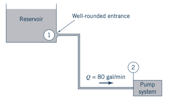
The piping system shown in the Figure (which does not show details of all the fittings) is used to connect a large reservoir to a pump where it is then pumped to a small wilderness hostel. The pipe is 2-in. I.D. cast iron and must deliver 80 gal/min of 60°F water. The 300 ft long pipeline contains four swing check valves and five 90° standard elbows. All connections are threaded. Find the head loss between points 1 and 2.
Homework Answers

Add Answer to:
The piping system shown in the Figure (which does not show
details of all the fittings)...
The piping system shown in the Figure (which does not show details of all the fittings)...
 The piping system shown in the Figure (which does not show details of all the fittings) is used to connect a large reservoir to a pump where it is then pumped to a small wilderness hostel. The pipe is 2-in. I.D. cast iron and must deliver 80 gal/min of 60°F water. The 300 ft long pipeline contains four swing check valves and five 90° standard elbows. All connections are threaded. Find the head loss between points 1 and 2. Well-rounded...
1/9 1 Piping system (14 points) Water is pumped from a reservoir to a large receiver...
 1/9 1 Piping system (14 points) Water is pumped from a reservoir to a large receiver vessel which is maintained at p4 6 bar (absolute) through the operation of the pump and a high pressure nitrogen supply that bleeds into the tank through a regulator. The water enters through an opening at the top of the vessel. A drain is provided at the low point in the system. Elevations are as shown. All valves are gate valves (k = 0.15)...
this is all of the information given Problem 3. A piping system consists of 1200 m...
 this is all of the information given
Problem 3. A piping system consists of 1200 m of 5 cm diameter cast-iron pipe, two 45° and four 90° flanged long-radius elbows, a fully open flanged globe valve, and a sharp submerged exit into a reservoir. The elevation of the outlet relative to the inlet is 100 m. What gage pressure is required at the inlet to deliver 0.005 m2/s of water at 20°C into the reservoir? Assume that the density and...
this is all of the information given
Problem 3. A piping system consists of 1200 m of 5 cm diameter cast-iron pipe, two 45° and four 90° flanged long-radius elbows, a fully open flanged globe valve, and a sharp submerged exit into a reservoir. The elevation of the outlet relative to the inlet is 100 m. What gage pressure is required at the inlet to deliver 0.005 m2/s of water at 20°C into the reservoir? Assume that the density and...
1. Water is pumped from a low reservoir to a high reservoir that is 20 m...
1. Water is pumped from a low reservoir to a high reservoir that is 20 m higher in elevation. The water is flowing at 1.5 m/s through a 305 mm internal diameter piping system. The water is at 18 degrees C. There are 1,000 m of piping, six standard 45 degree bends, two standard 90 degree bends, a branch flow tee, three gate valves, a swing check valve, a square inlet and a square outlet. The piping and valves are...
The total length of the piping system made of cast iron providing hot water to a...
 The total length of the piping system made of cast iron providing hot water to a house is considered to have a 42m length with a constant diameter. The entrance gage pressure is 85 kPa and exit at 15 kPa gaged. Consider the water density equal 980 Kg/m' and the viscosity 1.138x10 Kg/ms. a) Compute the piping system diameter if the volumetric flow rate provided by this system is equal to 0.1 L/s. There is no pump present in this...
) 25 points - Water flows in a piping system a section of which is shown...
 ) 25 points - Water flows in a piping system a section of which is shown below.Pipe is 30 mm ID commercial steel pipe. Velocity of flow is 1.6 m/s and is constant throughout. Pressure at Pt is 200 kPa. All the valves are fully open gate valves, all the elbows are regular 90° threaded. For water, p:1000 kg/m3, 0.00108 N-s/m2. Other necessary data is given on the diagram. Assume the flow is incompressible and steady. Determine the volume flow...
Question 6 - Minor Losses A tank and piping system is shown. The galvanized pipe diameter is 1.5 cm, and the total length of pipe is 10 m. The two 90° elbows are threaded fittings. The vertical dista...
 Question 6 - Minor Losses A tank and piping system is shown. The galvanized pipe diameter is 1.5 cm, and the total length of pipe is 10 m. The two 90° elbows are threaded fittings. The vertical distance from the water surface to the pipe outlet is 5 m. The velocity of the water in the tank is negligible. Find (a) the exit velocity of the water and (b) the height (h) the water jet would rise on exiting the...
Example of Pipe Sizing The figure shows a closed piping system to supply chilled water to two hea...
 Example of Pipe Sizing The figure shows a closed piping system to supply chilled water to two heat exchangers. Size the pipe for this system, assuming schedule-40 steel pipe is used with threaded (screwed) fitting. Determine the pump flow rate and head requirements. Distances are as shown in feet. Head losses through the heat exchangers and chiller are shown as provided by the manufacturers. Q(gpm) Head Loss (ft) 70 Unit Chiller Heat Exchanger (a) 30 Heat Exchanger (b) 40 12...
A pump transports water from Tank 1 to Tank 2 through a constant-diameter piping system as...
 A pump transports water from Tank 1 to Tank 2 through a constant-diameter piping system as shown below (not to scale). The flow rate is controlled by two gate valves, the gate valve I controls the main pipeline, while the gate valve II controls the loop line from T-joint A to T-joint B. All pipes are galvanized steel pipe of diameter D = 4 in. It has a total length of Li2= 620 ft from tank 1 to tank 2....
 The piping system shown in the Figure (which does not show details of all the fittings) is used to connect a large reservoir to a pump where it is then pumped to a small wilderness hostel. The pipe is 2-in. I.D. cast iron and must deliver 80 gal/min of 60°F water. The 300 ft long pipeline contains four swing check valves and five 90° standard elbows. All connections are threaded. Find the head loss between points 1 and 2. Well-rounded...
 1/9 1 Piping system (14 points) Water is pumped from a reservoir to a large receiver vessel which is maintained at p4 6 bar (absolute) through the operation of the pump and a high pressure nitrogen supply that bleeds into the tank through a regulator. The water enters through an opening at the top of the vessel. A drain is provided at the low point in the system. Elevations are as shown. All valves are gate valves (k = 0.15)...
 1/9 1 Piping system (14 points) Water is pumped from a reservoir to a large receiver vessel which is maintained at p4 6 bar (absolute) through the operation of the pump and a high pressure nitrogen supply that bleeds into the tank through a regulator. The water enters through an opening at the top of the vessel. A drain is provided at the low point in the system. Elevations are as shown. All valves are gate valves (k = 0.15)...
 this is all of the information given
Problem 3. A piping system consists of 1200 m of 5 cm diameter cast-iron pipe, two 45° and four 90° flanged long-radius elbows, a fully open flanged globe valve, and a sharp submerged exit into a reservoir. The elevation of the outlet relative to the inlet is 100 m. What gage pressure is required at the inlet to deliver 0.005 m2/s of water at 20°C into the reservoir? Assume that the density and...
this is all of the information given
Problem 3. A piping system consists of 1200 m of 5 cm diameter cast-iron pipe, two 45° and four 90° flanged long-radius elbows, a fully open flanged globe valve, and a sharp submerged exit into a reservoir. The elevation of the outlet relative to the inlet is 100 m. What gage pressure is required at the inlet to deliver 0.005 m2/s of water at 20°C into the reservoir? Assume that the density and...
 The total length of the piping system made of cast iron providing hot water to a house is considered to have a 42m length with a constant diameter. The entrance gage pressure is 85 kPa and exit at 15 kPa gaged. Consider the water density equal 980 Kg/m' and the viscosity 1.138x10 Kg/ms. a) Compute the piping system diameter if the volumetric flow rate provided by this system is equal to 0.1 L/s. There is no pump present in this...
 ) 25 points - Water flows in a piping system a section of which is shown below.Pipe is 30 mm ID commercial steel pipe. Velocity of flow is 1.6 m/s and is constant throughout. Pressure at Pt is 200 kPa. All the valves are fully open gate valves, all the elbows are regular 90° threaded. For water, p:1000 kg/m3, 0.00108 N-s/m2. Other necessary data is given on the diagram. Assume the flow is incompressible and steady. Determine the volume flow...
 Question 6 - Minor Losses A tank and piping system is shown. The galvanized pipe diameter is 1.5 cm, and the total length of pipe is 10 m. The two 90° elbows are threaded fittings. The vertical distance from the water surface to the pipe outlet is 5 m. The velocity of the water in the tank is negligible. Find (a) the exit velocity of the water and (b) the height (h) the water jet would rise on exiting the...
 Example of Pipe Sizing The figure shows a closed piping system to supply chilled water to two heat exchangers. Size the pipe for this system, assuming schedule-40 steel pipe is used with threaded (screwed) fitting. Determine the pump flow rate and head requirements. Distances are as shown in feet. Head losses through the heat exchangers and chiller are shown as provided by the manufacturers. Q(gpm) Head Loss (ft) 70 Unit Chiller Heat Exchanger (a) 30 Heat Exchanger (b) 40 12...
 A pump transports water from Tank 1 to Tank 2 through a constant-diameter piping system as shown below (not to scale). The flow rate is controlled by two gate valves, the gate valve I controls the main pipeline, while the gate valve II controls the loop line from T-joint A to T-joint B. All pipes are galvanized steel pipe of diameter D = 4 in. It has a total length of Li2= 620 ft from tank 1 to tank 2....
Most questions answered within 3 hours.
-
A solid, uniform disk of radius 0.250 m and mass 53.7 kg rolls
down a ramp...
asked 11 minutes ago -
Given the following table of high speed internet access vs.
annual home income:
Home Income
%...
asked 37 minutes ago -
A baseball batter hits a 0.145kg baseball straight up into the
air. The baseball leaves the...
asked 1 hour ago -
An FM modulator is tested using
single-tone baseband signal with frequency of 50kHz and a sprectrum...
asked 1 hour ago -
Write the ionic equations for the first stage of salts
hydrolysis.
Anion, Cation?
Na2S
NiSO4
K2SO4...
asked 3 hours ago -
suppose there is a normally distributed population with a mean of
250 and a standard deviation...
asked 3 hours ago -
Question Three
Suppose you as project manager are using the Waterfall
development methodology on a large...
asked 4 hours ago -
Which statement is not true about welfare in Canada?
A.Benefits typically vary based on one's ability...
asked 5 hours ago -
Please help me with FLOWCHART and UML diagram for class,
thank you!
#include <iostream>
#include <fstream>...
asked 6 hours ago -
3. Describe the “logic circuit” of the Lac operon. Which
proteins are bound or not to...
asked 6 hours ago -
Ayesha’s adjusted gross income is $60,000 in 2019. She donated a
piece of artwork with a...
asked 6 hours ago -
For Dijkstra’s shortest path algorithm:
a. Give the Big-O time for Dijkstra’s shortest path algorithm
and...
asked 6 hours ago