
Homework Answers
Add Answer to:
Consider the simply supported beam shown in the figure below. Let x be the distance measured...
the figure below. Let x be the distance measured from left Consider the simply supported beam...
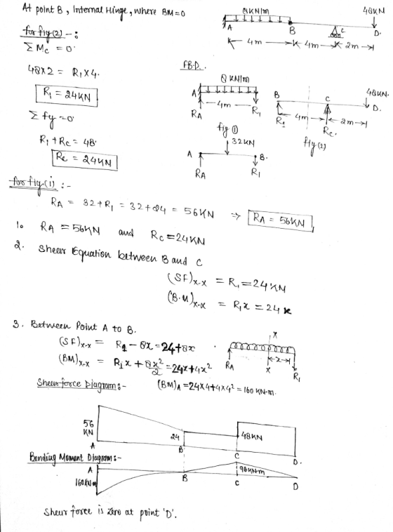
 the figure below. Let x be the distance measured from left Consider the simply supported beam shown end of the beam. 1. Determine the vertical reactions at A and C 2. Write the equations for shear and moment for the section of the member between B and C. 3. Draw the shear and moment diagrams for the entire beam, specifying values at changes in loading and locations where the shear is O. 48 KN 8 kN/m B с D internal...
Consider the simply supported beam shown in the figure below. Let x be the distance measured...
 Consider the simply supported beam shown in the figure below. Let x be the distance measured from left end of the beam. 1. Determine the vertical reactions at A and C 2. Write the equations for shear and moment for the section of the member between B and C. 3. Draw the shear and moment diagrams for the entire beam, specifying values at changes in loading and locations where the shear is 0. 48 KN 8 kN/m UT 24 kN-m...
Consider the simply supported beam shown in the figure below. Let x be the distance measured...
 Consider the simply supported beam shown in the figure below. Let x be the distance measured from left end of the beam. 1. Determine the vertical reactions at A and C 2. Write the equations for shear and moment for the section of the member between B and c. 3. Draw the shear and moment diagrams for the entire beam, specifying values at changes in loading and locations where the shear is 0. 8 kN/m 48 KN 24 KN-m MacBook...
Consider the simply supported beam shown in the figure below. Let xbe the distance measured from...
 Consider the simply supported beam shown in the figure below. Let xbe the distance measured from left end of the beam. 1. Determine the vertical reactions at A and C 2. Write the equations for shear and moment for the section of the member between B and C. 3. Draw the shear and moment diagrams for the entire beam, specifying values at changes in loading and locations where the shear is 0. 48 KN 8 kN/m 24 kN-m А B...
Consider the simply supported beam shown in the figure below. Let x be the distance measured...
 Consider the simply supported beam shown in the figure below. Let x be the distance measured from left end of the beam. 1. Determine the vertical reactions at A and C 2. Write the equations for shear and moment for the section of the şember between B and C. 3. Draw the shear and moment diagrams for the entire beam, specifying values at changes in loading and locations where the shear is 0. 8 kN/m 48 KN 24 N- MacBook...
20 Question 14 Consider the simply supported beam shown in the figure below. Let x be...
 20 Question 14 Consider the simply supported beam shown in the figure below. Let x be the distance measured from left end of the beam. 1. Determine the vertical reactions at A and C 2. Write the equations for shear and moment for the section of the member between B and C. 3. Draw the shear and moment diagrams for the entire beam, specifying values at changes in loading and locations where the shear is o. 8 kN/m 48 KN...
A simply supported beam as shown in the figure. The beam section is W18x211. The beam...
 A simply supported beam as shown in the figure. The beam section is W18x211. The beam must support its own weight and must carry the following loading: Super-imposed distributed dead load = 0.25 kip/ft Distributed live load = 1 kip/ft Concentrated dead load = 12 kip The beam span L = 26 ft and the distance of the concentrated load from the right support a=6 ft. Consider analy- sis of beam subjected to load combination 1.2 dead + 1.6 live....
QUESTION 1 [15] For the simply supported beam subjected to the loading shown in the figure,...
 QUESTION 1 [15] For the simply supported beam subjected to the loading shown in the figure, a) Derive equations for the shear force V and the bending moment M for any location in the beam. (Place the origin at point A.) b) Report the maximum positive bending moment, the maximum negative bending moment, and their respective locations. 36 KN 180 KN-m X B C D 4 m 5 m 3 m Figure 1
Shear force and bending moments of the beam. For the simply supported beam subjected to the...
 Shear force and bending moments of the beam.
For the simply supported beam subjected to the loading shown in Figure P7.8 derive equations for the shear force V and the bending moment M for any location in the beam. (Place the origin at point A.) plot the shear-force and bending-moment diagrams for the beam, using the derived functions. report the maximum positive bending moment, the maximum negative bending moment, and their respective locations.
Shear force and bending moments of the beam.
For the simply supported beam subjected to the loading shown in Figure P7.8 derive equations for the shear force V and the bending moment M for any location in the beam. (Place the origin at point A.) plot the shear-force and bending-moment diagrams for the beam, using the derived functions. report the maximum positive bending moment, the maximum negative bending moment, and their respective locations.
 the figure below. Let x be the distance measured from left Consider the simply supported beam shown end of the beam. 1. Determine the vertical reactions at A and C 2. Write the equations for shear and moment for the section of the member between B and C. 3. Draw the shear and moment diagrams for the entire beam, specifying values at changes in loading and locations where the shear is O. 48 KN 8 kN/m B с D internal...
 Consider the simply supported beam shown in the figure below. Let x be the distance measured from left end of the beam. 1. Determine the vertical reactions at A and C 2. Write the equations for shear and moment for the section of the member between B and C. 3. Draw the shear and moment diagrams for the entire beam, specifying values at changes in loading and locations where the shear is 0. 48 KN 8 kN/m UT 24 kN-m...
 Consider the simply supported beam shown in the figure below. Let x be the distance measured from left end of the beam. 1. Determine the vertical reactions at A and C 2. Write the equations for shear and moment for the section of the member between B and c. 3. Draw the shear and moment diagrams for the entire beam, specifying values at changes in loading and locations where the shear is 0. 8 kN/m 48 KN 24 KN-m MacBook...
 Consider the simply supported beam shown in the figure below. Let x be the distance measured from left end of the beam. 1. Determine the vertical reactions at A and C 2. Write the equations for shear and moment for the section of the member between B and c. 3. Draw the shear and moment diagrams for the entire beam, specifying values at changes in loading and locations where the shear is 0. 8 kN/m 48 KN 24 KN-m MacBook...
 Consider the simply supported beam shown in the figure below. Let xbe the distance measured from left end of the beam. 1. Determine the vertical reactions at A and C 2. Write the equations for shear and moment for the section of the member between B and C. 3. Draw the shear and moment diagrams for the entire beam, specifying values at changes in loading and locations where the shear is 0. 48 KN 8 kN/m 24 kN-m А B...
 Consider the simply supported beam shown in the figure below. Let x be the distance measured from left end of the beam. 1. Determine the vertical reactions at A and C 2. Write the equations for shear and moment for the section of the şember between B and C. 3. Draw the shear and moment diagrams for the entire beam, specifying values at changes in loading and locations where the shear is 0. 8 kN/m 48 KN 24 N- MacBook...
 20 Question 14 Consider the simply supported beam shown in the figure below. Let x be the distance measured from left end of the beam. 1. Determine the vertical reactions at A and C 2. Write the equations for shear and moment for the section of the member between B and C. 3. Draw the shear and moment diagrams for the entire beam, specifying values at changes in loading and locations where the shear is o. 8 kN/m 48 KN...
 A simply supported beam as shown in the figure. The beam section is W18x211. The beam must support its own weight and must carry the following loading: Super-imposed distributed dead load = 0.25 kip/ft Distributed live load = 1 kip/ft Concentrated dead load = 12 kip The beam span L = 26 ft and the distance of the concentrated load from the right support a=6 ft. Consider analy- sis of beam subjected to load combination 1.2 dead + 1.6 live....
 QUESTION 1 [15] For the simply supported beam subjected to the loading shown in the figure, a) Derive equations for the shear force V and the bending moment M for any location in the beam. (Place the origin at point A.) b) Report the maximum positive bending moment, the maximum negative bending moment, and their respective locations. 36 KN 180 KN-m X B C D 4 m 5 m 3 m Figure 1
 Shear force and bending moments of the beam.
For the simply supported beam subjected to the loading shown in Figure P7.8 derive equations for the shear force V and the bending moment M for any location in the beam. (Place the origin at point A.) plot the shear-force and bending-moment diagrams for the beam, using the derived functions. report the maximum positive bending moment, the maximum negative bending moment, and their respective locations.
Shear force and bending moments of the beam.
For the simply supported beam subjected to the loading shown in Figure P7.8 derive equations for the shear force V and the bending moment M for any location in the beam. (Place the origin at point A.) plot the shear-force and bending-moment diagrams for the beam, using the derived functions. report the maximum positive bending moment, the maximum negative bending moment, and their respective locations.
Most questions answered within 3 hours.
-
If you could afford exactly 6 apples and 14 bananas, or 10
apples and 6 bananas,...
asked 11 minutes ago -
Write functions squareByValue,
squareByRef, squareByPointer that find the square of an integer, in
three different ways:...
asked 6 minutes ago -
Find the P - value for the test statistic ?=2.74z=2.74
for the following null and alternative...
asked 12 minutes ago -
An software company has three different promotion plans for
its software purchase:
plan A: each software...
asked 32 minutes ago -
If
P(A)=.62, P(B)=.47, & P(A or B)=.88. What is the likeliness of
selecting only A?
A)...
asked 31 minutes ago -
What is the FUTURE VALUE of $500 invested for 3 years at 7% with
ANNUAL Compounding...
asked 40 minutes ago -
Modify the method so that instead of manually making teams, it
reads it from a text...
asked 39 minutes ago -
1. Which of the following is not a principle to apply to
construction:
Select one:
a....
asked 41 minutes ago -
In what way is a Christian’s position made more challenging by
revealing faith in the workplace?...
asked 48 minutes ago -
1) There are four categories of customer benefits in B2B
(business-to-business) markets. Which of the following...
asked 45 minutes ago -
What is the pH of a 150.0 mL solution of 0.0273 M NaOH (strong
base)?
asked 54 minutes ago -
A thin ball shell is shaped like a hollow ball with a radius of
26.6 cm....
asked 1 hour ago