
Homework Answers
a)
For Section BD

For section AB


b)


C)

Hope it helpful to you for any doubt comment below i will solve
your query
Rate my answer your rating is important to us
Add Answer to:
the figure below. Let x be the distance measured from left Consider the simply supported beam...
Consider the simply supported beam shown in the figure below. Let x be the distance measured...
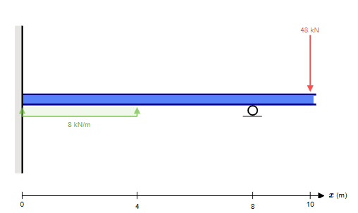
 Consider the simply supported beam shown in the figure below. Let x be the distance measured from left end of the beam. 1. Determine the vertical reactions at A and C 2. Write the equations for shear and moment for the section of the member between B and C. 3. Draw the shear and moment diagrams for the entire beam, specifying values at changes in loading and locations where the shear is 0. 48 KN B kN/m D internal pin...
Consider the simply supported beam shown in the figure below. Let x be the distance measured...
 Consider the simply supported beam shown in the figure below. Let x be the distance measured from left end of the beam. 1. Determine the vertical reactions at A and C 2. Write the equations for shear and moment for the section of the member between B and C. 3. Draw the shear and moment diagrams for the entire beam, specifying values at changes in loading and locations where the shear is 0. 48 KN 8 kN/m UT 24 kN-m...
Consider the simply supported beam shown in the figure below. Let xbe the distance measured from...
 Consider the simply supported beam shown in the figure below. Let xbe the distance measured from left end of the beam. 1. Determine the vertical reactions at A and C 2. Write the equations for shear and moment for the section of the member between B and C. 3. Draw the shear and moment diagrams for the entire beam, specifying values at changes in loading and locations where the shear is 0. 48 KN 8 kN/m 24 kN-m А B...
Consider the simply supported beam shown in the figure below. Let x be the distance measured...
 Consider the simply supported beam shown in the figure below. Let x be the distance measured from left end of the beam. 1. Determine the vertical reactions at A and C 2. Write the equations for shear and moment for the section of the member between B and c. 3. Draw the shear and moment diagrams for the entire beam, specifying values at changes in loading and locations where the shear is 0. 8 kN/m 48 KN 24 KN-m MacBook...
Consider the simply supported beam shown in the figure below. Let x be the distance measured...
 Consider the simply supported beam shown in the figure below. Let x be the distance measured from left end of the beam. 1. Determine the vertical reactions at A and C 2. Write the equations for shear and moment for the section of the şember between B and C. 3. Draw the shear and moment diagrams for the entire beam, specifying values at changes in loading and locations where the shear is 0. 8 kN/m 48 KN 24 N- MacBook...
20 Question 14 Consider the simply supported beam shown in the figure below. Let x be...
 20 Question 14 Consider the simply supported beam shown in the figure below. Let x be the distance measured from left end of the beam. 1. Determine the vertical reactions at A and C 2. Write the equations for shear and moment for the section of the member between B and C. 3. Draw the shear and moment diagrams for the entire beam, specifying values at changes in loading and locations where the shear is o. 8 kN/m 48 KN...
Shear force and bending moments of the beam. For the simply supported beam subjected to the...
 Shear force and bending moments of the beam.
For the simply supported beam subjected to the loading shown in Figure P7.8 derive equations for the shear force V and the bending moment M for any location in the beam. (Place the origin at point A.) plot the shear-force and bending-moment diagrams for the beam, using the derived functions. report the maximum positive bending moment, the maximum negative bending moment, and their respective locations.
Shear force and bending moments of the beam.
For the simply supported beam subjected to the loading shown in Figure P7.8 derive equations for the shear force V and the bending moment M for any location in the beam. (Place the origin at point A.) plot the shear-force and bending-moment diagrams for the beam, using the derived functions. report the maximum positive bending moment, the maximum negative bending moment, and their respective locations.
QUESTION 1 [15] For the simply supported beam subjected to the loading shown in the figure,...
 QUESTION 1 [15] For the simply supported beam subjected to the loading shown in the figure, a) Derive equations for the shear force V and the bending moment M for any location in the beam. (Place the origin at point A.) b) Report the maximum positive bending moment, the maximum negative bending moment, and their respective locations. 36 KN 180 KN-m X B C D 4 m 5 m 3 m Figure 1
04 m 8 KN 2. A simply supported beam is shown below. a. b. c. Draw...
 04 m 8 KN 2. A simply supported beam is shown below. a. b. c. Draw a proper FBD of the beam showing all the known and unknown forces acting on it. Determine the support reactions at A and B. Draw the shear (V) and bending moment (M) diagrams for the beam. 2500 lb 500 Ib/it 3 ft -3 ft 3 ft 3. Draw a proper FBD of member ABC showing all the known and unknown forces acting Determine the...
 Consider the simply supported beam shown in the figure below. Let x be the distance measured from left end of the beam. 1. Determine the vertical reactions at A and C 2. Write the equations for shear and moment for the section of the member between B and C. 3. Draw the shear and moment diagrams for the entire beam, specifying values at changes in loading and locations where the shear is 0. 48 KN B kN/m D internal pin...
 Consider the simply supported beam shown in the figure below. Let x be the distance measured from left end of the beam. 1. Determine the vertical reactions at A and C 2. Write the equations for shear and moment for the section of the member between B and C. 3. Draw the shear and moment diagrams for the entire beam, specifying values at changes in loading and locations where the shear is 0. 48 KN 8 kN/m UT 24 kN-m...
 Consider the simply supported beam shown in the figure below. Let xbe the distance measured from left end of the beam. 1. Determine the vertical reactions at A and C 2. Write the equations for shear and moment for the section of the member between B and C. 3. Draw the shear and moment diagrams for the entire beam, specifying values at changes in loading and locations where the shear is 0. 48 KN 8 kN/m 24 kN-m А B...
 Consider the simply supported beam shown in the figure below. Let x be the distance measured from left end of the beam. 1. Determine the vertical reactions at A and C 2. Write the equations for shear and moment for the section of the member between B and c. 3. Draw the shear and moment diagrams for the entire beam, specifying values at changes in loading and locations where the shear is 0. 8 kN/m 48 KN 24 KN-m MacBook...
 Consider the simply supported beam shown in the figure below. Let x be the distance measured from left end of the beam. 1. Determine the vertical reactions at A and C 2. Write the equations for shear and moment for the section of the member between B and c. 3. Draw the shear and moment diagrams for the entire beam, specifying values at changes in loading and locations where the shear is 0. 8 kN/m 48 KN 24 KN-m MacBook...
 Consider the simply supported beam shown in the figure below. Let x be the distance measured from left end of the beam. 1. Determine the vertical reactions at A and C 2. Write the equations for shear and moment for the section of the şember between B and C. 3. Draw the shear and moment diagrams for the entire beam, specifying values at changes in loading and locations where the shear is 0. 8 kN/m 48 KN 24 N- MacBook...
 20 Question 14 Consider the simply supported beam shown in the figure below. Let x be the distance measured from left end of the beam. 1. Determine the vertical reactions at A and C 2. Write the equations for shear and moment for the section of the member between B and C. 3. Draw the shear and moment diagrams for the entire beam, specifying values at changes in loading and locations where the shear is o. 8 kN/m 48 KN...
 Shear force and bending moments of the beam.
For the simply supported beam subjected to the loading shown in Figure P7.8 derive equations for the shear force V and the bending moment M for any location in the beam. (Place the origin at point A.) plot the shear-force and bending-moment diagrams for the beam, using the derived functions. report the maximum positive bending moment, the maximum negative bending moment, and their respective locations.
Shear force and bending moments of the beam.
For the simply supported beam subjected to the loading shown in Figure P7.8 derive equations for the shear force V and the bending moment M for any location in the beam. (Place the origin at point A.) plot the shear-force and bending-moment diagrams for the beam, using the derived functions. report the maximum positive bending moment, the maximum negative bending moment, and their respective locations.
 QUESTION 1 [15] For the simply supported beam subjected to the loading shown in the figure, a) Derive equations for the shear force V and the bending moment M for any location in the beam. (Place the origin at point A.) b) Report the maximum positive bending moment, the maximum negative bending moment, and their respective locations. 36 KN 180 KN-m X B C D 4 m 5 m 3 m Figure 1
 04 m 8 KN 2. A simply supported beam is shown below. a. b. c. Draw a proper FBD of the beam showing all the known and unknown forces acting on it. Determine the support reactions at A and B. Draw the shear (V) and bending moment (M) diagrams for the beam. 2500 lb 500 Ib/it 3 ft -3 ft 3 ft 3. Draw a proper FBD of member ABC showing all the known and unknown forces acting Determine the...
Most questions answered within 3 hours.
-
The group of companies LC "High-precision measuring instruments"
is the global provider of measurement, analysis and...
asked 57 seconds ago -
I want to write a python function to find the minimum
I have an nested list:...
asked 1 minute ago -
Convert the high level language programming statementts to 80x86
assembly, Assume X=AX and y=BX
for (i=1;...
asked 10 minutes ago -
SoleMate’s Burkins sneakers cost $40 per pair from the supplier
and are sold by SoleMate at...
asked 14 minutes ago -
The movie Moneyball (based on the book by Michael
Lewis) tells the story of Billy Beane,...
asked 13 minutes ago -
A regional highway uses 8 tollbooths that are open to all
vehicles. A chi-square goodness-of-fit test...
asked 16 minutes ago -
In her Semiannual Monetary Policy Report to Congress on July 13,
2017, then Federal Reserve Chair...
asked 16 minutes ago -
Suppose N packets are sent,
and each packet arrives at rate of L/2R to a link....
asked 35 minutes ago -
17. Show the steps involved in reduction of the ketone in fatty
acid synthesis. Which cofactor...
asked 36 minutes ago -
5.61 g of octane, C8H18, reacts with excess oxygen in a bomb
calorimeter. The heat capacity...
asked 40 minutes ago -
The velocity field of a flow is given by V = (2+1) x
y2 i +...
asked 49 minutes ago -
(EPS with
Convertible Bonds) On June 1, 2012, Bluhm Company and
Amanar Company merged to form...
asked 47 minutes ago