These are my measurements. This is for physics its a RC LAB. The purpose is that for a discharging capacitor we measure voltage and from this we determine the capacitance. Also from thee measured capacitance we can find thee internal resistance of the voltmeter
1)measurements over resistor
| T(time every 10 seconds | Voltage(V) |
| 1 | 5 |
| 2 | 4 |
| 3 | 2 |
| 4 | 1 |
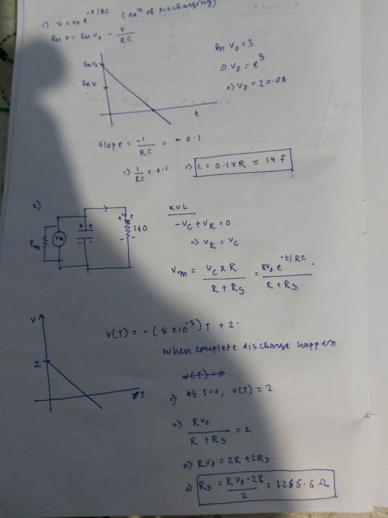
—>The wanted us to plot In(v) vs time, and find the equation of the line.The equation of line for this graph is -0.1x+3. The measured resistance I found was 140 ohm.
Question 1: How do I use the equations and the resistance I found to calculate the actual capacitance?
2)Measurements over the voltmeter
| T(eveery 10 sec) | Voltage (V) |
| 1 | 5 |
| 2 | 5.5 |
| 3 | 4 |
| 4 | 3.5 |
—>I graphed V vs T, and thee equation of the line I found was (-8*10^-3)x +2
Questions 2: using equation of the trendline and also the actual capacitance that was found in the first question to find the resistance thee voltmeter

Homework Answers
Add Answer to:
These are my measurements. This is for physics its a RC LAB. The
purpose is that...
An RC-circuit (Fig.1) contains components R and that need to be determined. You have a digital...
 An RC-circuit (Fig.1) contains components R and that need to be determined. You have a digital multi-meter (DMM) that can measure resistance (R), Voltage (V).etc., but not capacitance (C). To measure is not possible, 50 You can determine c from the time-courtone G-RC of the circuit. For this, you design av experiment: A known voltage V (say, Vo=97 from a qv batery) 25 applied to the circuit, then you mearure the voltage across the capacitor, say, you necard valt) every...
1. What does the time constant of an RC circuit that is being charged tell you?
 Background Summary Questions: 1. What does the time constant of an RC circuit that is being charged tell you? 2. What does the time constant of an RC circuit that is being discharged tell you? 3. How is the voltage across the capacitor related to the charge on a capacitor? (Linear, Inverse, Quadratic, etc.) 4. Based on your answer to question 3, how would you write an expression for the voltage across the capacitor as a function of time? a. Charging: V(t) b. Discharging: V(t)= Background: The...
8. Capacitance in circuits, RC circuits When a voltage source Vo is applied to a capacitor...
 8. Capacitance in circuits, RC circuits When a voltage source Vo is applied to a capacitor in a circuit which has a resistance R, a charge Q CV will build up across the capacitor. This does not happen instantaneously, but takes some time. The charge builds up exponentially with a characteristic time r = RC. Charging: V = v. 1 - e-t/RC) Discharging: Vc = V e-t/RC Page 2 of 3 When t = RC , the exponential is lle,...
An RC circuit is shown. The equivalent capacitance for the capacitor network is Cac = 12...
 An RC circuit is shown. The equivalent capacitance for the capacitor network is Cac = 12 uF. The equivalent resistance for the resistor network is Rce = 800 12 The capacitors are initially uncharged, and the switch S is closed at t = 0. a) Find C3. [4 points] b) Find R1: [4 points] c) Find the current i(0) in the circuit at t= 0. [4 points] d) Find Vac in the circuit at t = 00. [3 points] e)...
Construct a RC circuit (series) with a capacitor, a resistor, a battery,
 Part A Charging of RC Circuit 1) Construct a RC circuit (series) with a capacitor, a resistor, a battery, two switches, and appropriate meters that will enable you to make measurements of the parameters for charging up the capacitor. The placement of the switches allows you to measure both charging and discharging of the RC circuit. See diagram below: 2) Choose a combination of Rand C that will give you a time constant(T) of 20 seconds. T=R*C 20= 100* C=0.2F 3) Set the...
I am working on my Physics lab report where it was all about Direct Current Measurement...
I am working on my Physics lab report where it was all about Direct Current Measurement and Ohm’s Law. We had 5 different resistors and had to construct different circuits using a power supply, volt-ohm-milliammeter (VOM) and a digital multimeter to get measurements of resistance, voltage, and current. Nominal values of resistance and tolerance Resistor Nominal Resistance (Ohms) Tolerance (Ohms) R1 680 +/- 68 R2 1000 +/- 50 R3 1500 +/- 75 R4 4700 +/- 470 R5 10,000 +/- 500...
| -/1 points v SERCP11 18.5.P.036. My Notes Ask Your Teacher v The RC charging circuit...
 | -/1 points v SERCP11 18.5.P.036. My Notes Ask Your Teacher v The RC charging circuit in a camera flash unit has a voltage source of 285 V and a capacitance of 141 uF. HINT (a) Find its resistance R (in ohms) if the capacitor charges to 90.0% of its final value in 14.2 s. (b) Find the average current (in A) delivered to the flash bulb if the capacitor discharges 90.0% of its full charge in 1.34 ms. ГА
Name: ENGT 3050 Fundamentals of Electricity LAB EXERCISE #3 Series and Parallel Circuits Objectives: The objective...
 Name: ENGT 3050 Fundamentals of Electricity LAB EXERCISE #3 Series and Parallel Circuits Objectives: The objective of this exercise is to examine Kirchhoff's Voltage and Current Laws. Kirchhoff's Voltage Law (KVL) states, for a closed loop series path the algebraic sum of all the voltages around any closed loop in a circuit is equal to zero. Kirchhoff's Current Law (KCL) states, for a parallel path the total current entering a circuits junction is exactly equal to the total current leaving...
1. What is the vacRMS Voltage for the signal shown below? 10 V 2 V 2....
 1. What is the vacRMS Voltage for the signal shown below? 10 V 2 V 2. An AC voltage of 12vacaMs is equal to what peak to peak voltage? 3. In a purely resistive AC circuit where 10vacpK-PK is applied across an 8-ohm resistor, the current is 4. The total capacitance of a 330HF capacitor connected in parallel with a 470 uF capacitor is If an ac signal has a frequency of 125kHz, how much time does it take for...
Part II. Conversion of a Galvanometer into a Voltmeter a) Let's now switch to the circuit...
 Part II. Conversion of a Galvanometer into a Voltmeter a) Let's now switch to the circuit in Figure 2. Set it up and have it checked by your instructor before closing it. For Rause the theostat (from the greck p owitam resistance of 2000 Calculate the resistance Raneeded to make your 0-1.0 mA galvanometer work as a Qur voltmeter (neglect Ro) and insert it in the circuit 3U RM" .3k-2 b) Use your voltmeter to measure the voltage of 1...
 An RC-circuit (Fig.1) contains components R and that need to be determined. You have a digital multi-meter (DMM) that can measure resistance (R), Voltage (V).etc., but not capacitance (C). To measure is not possible, 50 You can determine c from the time-courtone G-RC of the circuit. For this, you design av experiment: A known voltage V (say, Vo=97 from a qv batery) 25 applied to the circuit, then you mearure the voltage across the capacitor, say, you necard valt) every...
 Background Summary Questions: 1. What does the time constant of an RC circuit that is being charged tell you? 2. What does the time constant of an RC circuit that is being discharged tell you? 3. How is the voltage across the capacitor related to the charge on a capacitor? (Linear, Inverse, Quadratic, etc.) 4. Based on your answer to question 3, how would you write an expression for the voltage across the capacitor as a function of time? a. Charging: V(t) b. Discharging: V(t)= Background: The...
 8. Capacitance in circuits, RC circuits When a voltage source Vo is applied to a capacitor in a circuit which has a resistance R, a charge Q CV will build up across the capacitor. This does not happen instantaneously, but takes some time. The charge builds up exponentially with a characteristic time r = RC. Charging: V = v. 1 - e-t/RC) Discharging: Vc = V e-t/RC Page 2 of 3 When t = RC , the exponential is lle,...
 An RC circuit is shown. The equivalent capacitance for the capacitor network is Cac = 12 uF. The equivalent resistance for the resistor network is Rce = 800 12 The capacitors are initially uncharged, and the switch S is closed at t = 0. a) Find C3. [4 points] b) Find R1: [4 points] c) Find the current i(0) in the circuit at t= 0. [4 points] d) Find Vac in the circuit at t = 00. [3 points] e)...
 Part A Charging of RC Circuit 1) Construct a RC circuit (series) with a capacitor, a resistor, a battery, two switches, and appropriate meters that will enable you to make measurements of the parameters for charging up the capacitor. The placement of the switches allows you to measure both charging and discharging of the RC circuit. See diagram below: 2) Choose a combination of Rand C that will give you a time constant(T) of 20 seconds. T=R*C 20= 100* C=0.2F 3) Set the...
 | -/1 points v SERCP11 18.5.P.036. My Notes Ask Your Teacher v The RC charging circuit in a camera flash unit has a voltage source of 285 V and a capacitance of 141 uF. HINT (a) Find its resistance R (in ohms) if the capacitor charges to 90.0% of its final value in 14.2 s. (b) Find the average current (in A) delivered to the flash bulb if the capacitor discharges 90.0% of its full charge in 1.34 ms. ГА
 Name: ENGT 3050 Fundamentals of Electricity LAB EXERCISE #3 Series and Parallel Circuits Objectives: The objective of this exercise is to examine Kirchhoff's Voltage and Current Laws. Kirchhoff's Voltage Law (KVL) states, for a closed loop series path the algebraic sum of all the voltages around any closed loop in a circuit is equal to zero. Kirchhoff's Current Law (KCL) states, for a parallel path the total current entering a circuits junction is exactly equal to the total current leaving...
 1. What is the vacRMS Voltage for the signal shown below? 10 V 2 V 2. An AC voltage of 12vacaMs is equal to what peak to peak voltage? 3. In a purely resistive AC circuit where 10vacpK-PK is applied across an 8-ohm resistor, the current is 4. The total capacitance of a 330HF capacitor connected in parallel with a 470 uF capacitor is If an ac signal has a frequency of 125kHz, how much time does it take for...
 Part II. Conversion of a Galvanometer into a Voltmeter a) Let's now switch to the circuit in Figure 2. Set it up and have it checked by your instructor before closing it. For Rause the theostat (from the greck p owitam resistance of 2000 Calculate the resistance Raneeded to make your 0-1.0 mA galvanometer work as a Qur voltmeter (neglect Ro) and insert it in the circuit 3U RM" .3k-2 b) Use your voltmeter to measure the voltage of 1...
Most questions answered within 3 hours.
-
Hello,
Can you assist with the 2 part multiple choice question?
1A) Which of the following...
asked 8 minutes ago -
A municipal bond you are considering as an investment currently
pays a yield of 6.82 percent....
asked 13 minutes ago -
My Ebook is already expired. How could I keep using it since it
is very helpfull...
asked 20 minutes ago -
describe in detail your "perfect" place to study in your home
giving great detail to how...
asked 37 minutes ago -
Decide with a brief explanation of the following statements
about reaction rates and catalysis are true:...
asked 39 minutes ago -
Write a grading program in Java for a class with the following
grading policies: There are...
asked 41 minutes ago -
Can someone explain the process of this Display a text
file program and show the supposed...
asked 54 minutes ago -
When a solid dissolves in water, heat may be evolved or
absorbed. The heat of dissolution...
asked 56 minutes ago -
Leechtown Co. has 4.3 percent coupon bonds on the market with 18
years left to maturity....
asked 58 minutes ago -
Comment on how the conference could have been improved What
additional elements would you consider adding...
asked 1 hour ago -
Sandra Clothing Company has invested $51,000,000 in its
business. The target rate of return for the...
asked 1 hour ago -
"Discover the privacy concerns when applying Artificial
Intelligence into Big Data"
asked 1 hour ago