
Homework Answers
Add Answer to:
f(2x)=? f(?x)2= ? m(?)2 =?
5.14 For the rigid frame shown in Figure P5-14, determine the...
rigid frames
 For the rigid frames shown in Figures P5–5 through P5–15, determine the displacements and rotations of the nodes, the element forces, and the reactions. The values of E;A, and I to be used are listed next to each figure.
problem 5-10 For the rigid frames shown in Figure, determine the displacements and rotations of the nodes the element forces, and the reactions. The values of E, A, and /to be used are listed next to...
 problem 5-10
For the rigid frames shown in Figure, determine the displacements and rotations of the nodes the element forces, and the reactions. The values of E, A, and /to be used are listed next to each figure. 10 KN E 210 GPa A x 10-2m 2 x 10-m O kN- m 10 kN Tm 5 kN m 45°
For the rigid frames shown in Figure, determine the displacements and rotations of the nodes the element forces, and the reactions....
problem 5-10
For the rigid frames shown in Figure, determine the displacements and rotations of the nodes the element forces, and the reactions. The values of E, A, and /to be used are listed next to each figure. 10 KN E 210 GPa A x 10-2m 2 x 10-m O kN- m 10 kN Tm 5 kN m 45°
For the rigid frames shown in Figure, determine the displacements and rotations of the nodes the element forces, and the reactions....
For the rigid frames shown in Figures P5-5 through P5-15, determine the displace- ments and rotations...
 For the rigid frames shown in Figures P5-5 through P5-15, determine the displace- ments and rotations of the nodes, the clement forces, and the reactions. The values of E. A, and I to be used are listed next to each figure. 25 kN/m In 4.5 m E= 210 GPa 450 1-8 x 10 m
For the rigid frame shown in figures, determine (1) the nodal displacements and rotations of the...
 For the rigid frame shown in figures, determine (1) the nodal displacements and rotations of the nodes, (2) the reactions, and (3) the forces in each element. 20 ft 5000 30x 10p A-10 in 200 in (for elements 1 2 and 3) 20 ft 0 1 in 4-2 in
Solve all problems using the finite element stiffness method. For the rigid frame shown in Figure P5-4, determine (1) the nodal displacements and rotation at node 4, (2) the reactions, and (3) the fo...
 Solve all problems using the finite element stiffness method. For the rigid frame shown in Figure P5-4, determine (1) the nodal displacements and rotation at node 4, (2) the reactions, and (3) the forces in each element. Then check equilibrium at node 4 Finally, draw the shear force and bending moment diagrams for each element. Let E 30x 103 ksi, A 8 in2, and I 800 in.4 for all elements. 20 kip 25 ft 25 ft 40 ft Figure P5-4...
Solve all problems using the finite element stiffness method. For the rigid frame shown in Figure...
 Solve all problems using the finite element stiffness method. For the rigid frame shown in Figure P5-4, determine (1) the nodal displacements and rotation at node 4, (2) the reactions, and (3) the forces in each element. Then check equilibrium at node 4. Finally, draw the shear force and bending moment diagrams for each element. LetE 30 x 103 ksi, A = 8 in,2 , and 1-800 in.4 for all elements. 20 kip 25 ft 25 ft- 40 ft 20...
For the beam shown in below, determine the displacements and rotations at the nodes, the forces in each element, and reactions. Also, draw the shear force and bending moment diagrams 10 kN 2 E210 GPa...
 For the beam shown in below, determine the displacements and rotations at the nodes, the forces in each element, and reactions. Also, draw the shear force and bending moment diagrams 10 kN 2 E210 GPa .20 kN m
For the beam shown in below, determine the displacements and rotations at the nodes, the forces in each element, and reactions. Also, draw the shear force and bending moment diagrams 10 kN 2 E210 GPa .20 kN m
For the beam shown in below, determine the displacements and rotations at the nodes, the forces in each element, and reactions. Also, draw the shear force and bending moment diagrams 10 kN 2 E210 GPa .20 kN m
0.2 The axially rigid frame ABCD shown in Figure 0.2 is fully fixed to A, and...
 0.2 The axially rigid frame ABCD shown in Figure 0.2 is fully fixed to A, and supported at Cand D as shown. The degrees of freedom are indicated on the frame. (1) The structural stiffness matrix [K] is related to the applied load vector [P] and the structural displacement vector [4] by: [P] = [K] 141 Construct the structural stiffness matrix [K] and the applied load vector [P] necessary to calculate the structural displacements. (18) (1) Each element stiffness matrix...
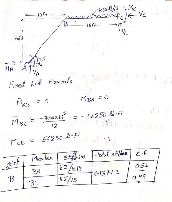
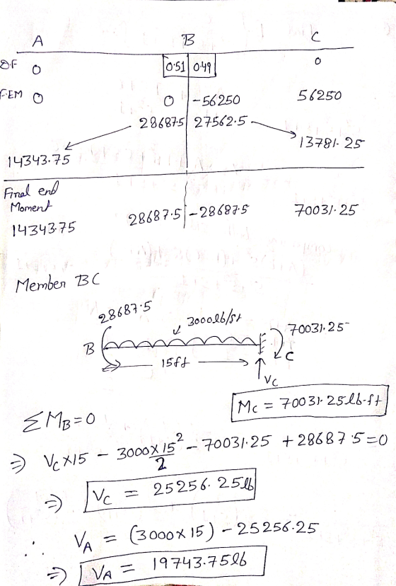
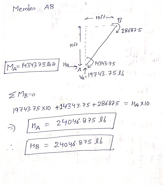
Question 1 A plane frame is loaded as shown in the figure below. The global coordinate axes are shown in the figure...
 Question 1 A plane frame is loaded as shown in the figure below. The global coordinate axes are shown in the figure. For both elements, E = 30000 ksi, I-1000 in4 and A-100 in2. Determine all nodal displacements, nodal rotations and member end forces (including moments) for both members. Label member end forces in a free body diagram 1000 lb/ft 40 ft 45 30 ft
by finite elemnt method 4. (25 points) Using symmetry on the frame shown below, solve for...
 by finite elemnt method
4. (25 points) Using symmetry on the frame shown below, solve for the unknown displacements and rotations. When setting up the stiffness matrix you may neglect terms that would be used to find the reactions. Use a consistent unit system from the table below. Note, the connections at nodes 2 and 4 are pins that do not allow X and Y displacements but do allow rotations. 60 KN 2 100 KN m 3 3 100 kNm...
by finite elemnt method
4. (25 points) Using symmetry on the frame shown below, solve for the unknown displacements and rotations. When setting up the stiffness matrix you may neglect terms that would be used to find the reactions. Use a consistent unit system from the table below. Note, the connections at nodes 2 and 4 are pins that do not allow X and Y displacements but do allow rotations. 60 KN 2 100 KN m 3 3 100 kNm...
 problem 5-10
For the rigid frames shown in Figure, determine the displacements and rotations of the nodes the element forces, and the reactions. The values of E, A, and /to be used are listed next to each figure. 10 KN E 210 GPa A x 10-2m 2 x 10-m O kN- m 10 kN Tm 5 kN m 45°
For the rigid frames shown in Figure, determine the displacements and rotations of the nodes the element forces, and the reactions....
problem 5-10
For the rigid frames shown in Figure, determine the displacements and rotations of the nodes the element forces, and the reactions. The values of E, A, and /to be used are listed next to each figure. 10 KN E 210 GPa A x 10-2m 2 x 10-m O kN- m 10 kN Tm 5 kN m 45°
For the rigid frames shown in Figure, determine the displacements and rotations of the nodes the element forces, and the reactions....
 For the rigid frames shown in Figures P5-5 through P5-15, determine the displace- ments and rotations of the nodes, the clement forces, and the reactions. The values of E. A, and I to be used are listed next to each figure. 25 kN/m In 4.5 m E= 210 GPa 450 1-8 x 10 m
 For the rigid frame shown in figures, determine (1) the nodal displacements and rotations of the nodes, (2) the reactions, and (3) the forces in each element. 20 ft 5000 30x 10p A-10 in 200 in (for elements 1 2 and 3) 20 ft 0 1 in 4-2 in
 Solve all problems using the finite element stiffness method. For the rigid frame shown in Figure P5-4, determine (1) the nodal displacements and rotation at node 4, (2) the reactions, and (3) the forces in each element. Then check equilibrium at node 4 Finally, draw the shear force and bending moment diagrams for each element. Let E 30x 103 ksi, A 8 in2, and I 800 in.4 for all elements. 20 kip 25 ft 25 ft 40 ft Figure P5-4...
 Solve all problems using the finite element stiffness method. For the rigid frame shown in Figure P5-4, determine (1) the nodal displacements and rotation at node 4, (2) the reactions, and (3) the forces in each element. Then check equilibrium at node 4. Finally, draw the shear force and bending moment diagrams for each element. LetE 30 x 103 ksi, A = 8 in,2 , and 1-800 in.4 for all elements. 20 kip 25 ft 25 ft- 40 ft 20...
 For the beam shown in below, determine the displacements and rotations at the nodes, the forces in each element, and reactions. Also, draw the shear force and bending moment diagrams 10 kN 2 E210 GPa .20 kN m
For the beam shown in below, determine the displacements and rotations at the nodes, the forces in each element, and reactions. Also, draw the shear force and bending moment diagrams 10 kN 2 E210 GPa .20 kN m
For the beam shown in below, determine the displacements and rotations at the nodes, the forces in each element, and reactions. Also, draw the shear force and bending moment diagrams 10 kN 2 E210 GPa .20 kN m
 0.2 The axially rigid frame ABCD shown in Figure 0.2 is fully fixed to A, and supported at Cand D as shown. The degrees of freedom are indicated on the frame. (1) The structural stiffness matrix [K] is related to the applied load vector [P] and the structural displacement vector [4] by: [P] = [K] 141 Construct the structural stiffness matrix [K] and the applied load vector [P] necessary to calculate the structural displacements. (18) (1) Each element stiffness matrix...
 Question 1 A plane frame is loaded as shown in the figure below. The global coordinate axes are shown in the figure. For both elements, E = 30000 ksi, I-1000 in4 and A-100 in2. Determine all nodal displacements, nodal rotations and member end forces (including moments) for both members. Label member end forces in a free body diagram 1000 lb/ft 40 ft 45 30 ft
 by finite elemnt method
4. (25 points) Using symmetry on the frame shown below, solve for the unknown displacements and rotations. When setting up the stiffness matrix you may neglect terms that would be used to find the reactions. Use a consistent unit system from the table below. Note, the connections at nodes 2 and 4 are pins that do not allow X and Y displacements but do allow rotations. 60 KN 2 100 KN m 3 3 100 kNm...
by finite elemnt method
4. (25 points) Using symmetry on the frame shown below, solve for the unknown displacements and rotations. When setting up the stiffness matrix you may neglect terms that would be used to find the reactions. Use a consistent unit system from the table below. Note, the connections at nodes 2 and 4 are pins that do not allow X and Y displacements but do allow rotations. 60 KN 2 100 KN m 3 3 100 kNm...
Most questions answered within 3 hours.
-
A simple random sample of size n=64 is obtained from a
population with a mean of...
asked 11 minutes ago -
(2 dimensions, 1 object, 2 accelerations)
1) A projectile is thrown with a wind. The wind...
asked 58 minutes ago -
Brian makes $34,100 per year. How much can Brian expect to
contribute to FICA taxes in...
asked 1 hour ago -
To buy a new house you must borrow $155,000. To do this you take
out a...
asked 1 hour ago -
Spacely Sprockets is evaluating the construction of a new plant
on land the company purchased for...
asked 2 hours ago -
1. Consider a linear regression model of y on K regressors and
an intercept.
(i) Describe...
asked 2 hours ago -
Enter a balanced equation for the reaction between hydrochloric
acid and sodium sulfite.
Express your answer...
asked 2 hours ago -
Give a regular expression describing the language
{x | x ∈ Σ* and x does not...
asked 2 hours ago -
Masses of 1.0 kg, 2.0 kg, and 3.0 kg are each separately subject
to a net...
asked 3 hours ago -
The mode of philosophical argumentation and thought. How do
philosophers think and write? What is important...
asked 3 hours ago -
At the beginning of the unit, you were asked whether you thought
it was appropriate or...
asked 3 hours ago -
Calculate the grams of carbon in 9.32 x 10+23 molecules of
benzene (C6H6).
asked 3 hours ago