
Homework Answers
Add Answer to:
problem 5-10 For the rigid frames shown in Figure, determine the displacements and rotations of the nodes the element forces, and the reactions. The values of E, A, and /to be used are listed next to...
For the rigid frames shown in Figures P5-5 through P5-15, determine the displace- ments and rotations...
 For the rigid frames shown in Figures P5-5 through P5-15, determine the displace- ments and rotations of the nodes, the clement forces, and the reactions. The values of E. A, and I to be used are listed next to each figure. 25 kN/m In 4.5 m E= 210 GPa 450 1-8 x 10 m
rigid frames
 For the rigid frames shown in Figures P5–5 through P5–15, determine the displacements and rotations of the nodes, the element forces, and the reactions. The values of E;A, and I to be used are listed next to each figure.
For the beam shown in below, determine the displacements and rotations at the nodes, the forces in each element, and reactions. Also, draw the shear force and bending moment diagrams 10 kN 2 E210 GPa...
 For the beam shown in below, determine the displacements and rotations at the nodes, the forces in each element, and reactions. Also, draw the shear force and bending moment diagrams 10 kN 2 E210 GPa .20 kN m
For the beam shown in below, determine the displacements and rotations at the nodes, the forces in each element, and reactions. Also, draw the shear force and bending moment diagrams 10 kN 2 E210 GPa .20 kN m
For the beam shown in below, determine the displacements and rotations at the nodes, the forces in each element, and reactions. Also, draw the shear force and bending moment diagrams 10 kN 2 E210 GPa .20 kN m
f(2x)=? f(?x)2= ? m(?)2 =? 5.14 For the rigid frame shown in Figure P5-14, determine the...
 f(2x)=? f(?x)2= ? m(?)2 =?
5.14 For the rigid frame shown in Figure P5-14, determine the displacements and rotations of the nodes, the element forces, and the reactions. Use the values of E, A, and I listed in the Figure. © 15 10 E = 30 x 10 Asin
f(2x)=? f(?x)2= ? m(?)2 =?
5.14 For the rigid frame shown in Figure P5-14, determine the displacements and rotations of the nodes, the element forces, and the reactions. Use the values of E, A, and I listed in the Figure. © 15 10 E = 30 x 10 Asin
structural analysis Figure Q() Question 2 For the bar assemblages shown in Figure Q(2), determine the nodal displacements, the forces in each element and the reactions. Use the direct stiffness me...
 structural analysis
Figure Q() Question 2 For the bar assemblages shown in Figure Q(2), determine the nodal displacements, the forces in each element and the reactions. Use the direct stiffness method (25 marks) 35 kN E-210 GPa 2 A4 x 10m2 1 m im
Figure Q() Question 2 For the bar assemblages shown in Figure Q(2), determine the nodal displacements, the forces in each element and the reactions. Use the direct stiffness method (25 marks) 35 kN E-210 GPa 2...
structural analysis
Figure Q() Question 2 For the bar assemblages shown in Figure Q(2), determine the nodal displacements, the forces in each element and the reactions. Use the direct stiffness method (25 marks) 35 kN E-210 GPa 2 A4 x 10m2 1 m im
Figure Q() Question 2 For the bar assemblages shown in Figure Q(2), determine the nodal displacements, the forces in each element and the reactions. Use the direct stiffness method (25 marks) 35 kN E-210 GPa 2...
For the rigid frame shown in figures, determine (1) the nodal displacements and rotations of the...
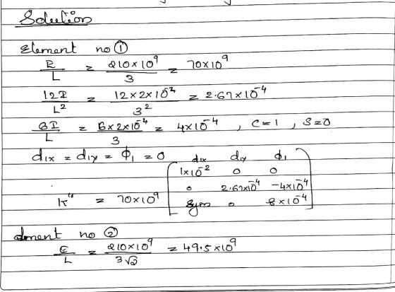
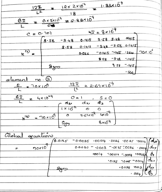
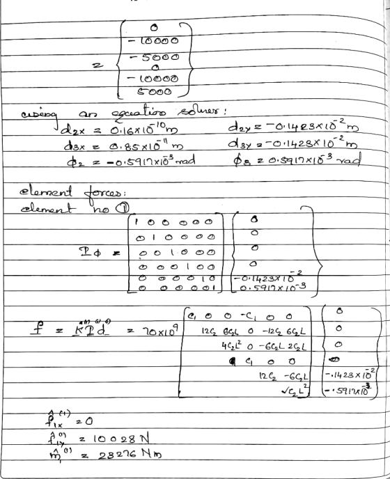
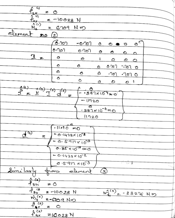
 For the rigid frame shown in figures, determine (1) the nodal displacements and rotations of the nodes, (2) the reactions, and (3) the forces in each element. 20 ft 5000 30x 10p A-10 in 200 in (for elements 1 2 and 3) 20 ft 0 1 in 4-2 in
Problem 4, (20%) For the case shown determine the displacements and the slopes at the nodes,...
 Problem 4, (20%) For the case shown determine the displacements and the slopes at the nodes, the forces in each element, and the reactions. Also, draw the shear force and bending moment diagrams. 24 KN 4 m 4 m E = 70 GPa 1 = 2 x 10⁻⁴ m > k = 200 kN/m
Problem 2: a. For the plane truss shown in Figure 2, determine the nodal displacements, the element forces and stresses, and the support reactions. All elements have E-70 GPa and A-25 cm 100 k...
 Problem 2: a. For the plane truss shown in Figure 2, determine the nodal displacements, the element forces and stresses, and the support reactions. All elements have E-70 GPa and A-25 cm 100 kN 50 kN 50 kN 4 4 6 Figure 2. Plane Truss
Problem 2: a. For the plane truss shown in Figure 2, determine the nodal displacements, the element forces and stresses, and the support reactions. All elements have E-70 GPa and A-25 cm 100 kN 50...
Problem 2: a. For the plane truss shown in Figure 2, determine the nodal displacements, the element forces and stresses, and the support reactions. All elements have E-70 GPa and A-25 cm 100 kN 50 kN 50 kN 4 4 6 Figure 2. Plane Truss
Problem 2: a. For the plane truss shown in Figure 2, determine the nodal displacements, the element forces and stresses, and the support reactions. All elements have E-70 GPa and A-25 cm 100 kN 50...
Problem 2: For the beam shown in below figure, determine the nodal displacements and slopes, the...
 Problem 2: For the beam shown in below figure, determine the nodal displacements and slopes, the forces in each element, and the reactions. 4 kN/ Im E 70 GPa 13 x 10-4 m4 4 m
Determine the nodal displacements and find the reaction forces using the finite element method. Correct Answer:...
 Determine the nodal displacements and find the reaction forces
using the finite element method.
Correct Answer:
1 m 1000 kN - Determine displacements and reactions E = 210 GPa 1 for 1 and 2 A=6x10⁻⁴ m| E = 210 GPa 1 m →X A=672x10-4 m2 for 3 d2x = 11.91x10-m; dăx = 5.613x10-'m . Fix =-500kN; F1, =-500kN; F2y = 0; F;, = 707 kN
Determine the nodal displacements and find the reaction forces
using the finite element method.
Correct Answer:
1 m 1000 kN - Determine displacements and reactions E = 210 GPa 1 for 1 and 2 A=6x10⁻⁴ m| E = 210 GPa 1 m →X A=672x10-4 m2 for 3 d2x = 11.91x10-m; dăx = 5.613x10-'m . Fix =-500kN; F1, =-500kN; F2y = 0; F;, = 707 kN
 For the rigid frames shown in Figures P5-5 through P5-15, determine the displace- ments and rotations of the nodes, the clement forces, and the reactions. The values of E. A, and I to be used are listed next to each figure. 25 kN/m In 4.5 m E= 210 GPa 450 1-8 x 10 m
 For the beam shown in below, determine the displacements and rotations at the nodes, the forces in each element, and reactions. Also, draw the shear force and bending moment diagrams 10 kN 2 E210 GPa .20 kN m
For the beam shown in below, determine the displacements and rotations at the nodes, the forces in each element, and reactions. Also, draw the shear force and bending moment diagrams 10 kN 2 E210 GPa .20 kN m
For the beam shown in below, determine the displacements and rotations at the nodes, the forces in each element, and reactions. Also, draw the shear force and bending moment diagrams 10 kN 2 E210 GPa .20 kN m
 f(2x)=? f(?x)2= ? m(?)2 =?
5.14 For the rigid frame shown in Figure P5-14, determine the displacements and rotations of the nodes, the element forces, and the reactions. Use the values of E, A, and I listed in the Figure. © 15 10 E = 30 x 10 Asin
f(2x)=? f(?x)2= ? m(?)2 =?
5.14 For the rigid frame shown in Figure P5-14, determine the displacements and rotations of the nodes, the element forces, and the reactions. Use the values of E, A, and I listed in the Figure. © 15 10 E = 30 x 10 Asin
 structural analysis
Figure Q() Question 2 For the bar assemblages shown in Figure Q(2), determine the nodal displacements, the forces in each element and the reactions. Use the direct stiffness method (25 marks) 35 kN E-210 GPa 2 A4 x 10m2 1 m im
Figure Q() Question 2 For the bar assemblages shown in Figure Q(2), determine the nodal displacements, the forces in each element and the reactions. Use the direct stiffness method (25 marks) 35 kN E-210 GPa 2...
structural analysis
Figure Q() Question 2 For the bar assemblages shown in Figure Q(2), determine the nodal displacements, the forces in each element and the reactions. Use the direct stiffness method (25 marks) 35 kN E-210 GPa 2 A4 x 10m2 1 m im
Figure Q() Question 2 For the bar assemblages shown in Figure Q(2), determine the nodal displacements, the forces in each element and the reactions. Use the direct stiffness method (25 marks) 35 kN E-210 GPa 2...
 For the rigid frame shown in figures, determine (1) the nodal displacements and rotations of the nodes, (2) the reactions, and (3) the forces in each element. 20 ft 5000 30x 10p A-10 in 200 in (for elements 1 2 and 3) 20 ft 0 1 in 4-2 in
 Problem 4, (20%) For the case shown determine the displacements and the slopes at the nodes, the forces in each element, and the reactions. Also, draw the shear force and bending moment diagrams. 24 KN 4 m 4 m E = 70 GPa 1 = 2 x 10⁻⁴ m > k = 200 kN/m
 Problem 2: a. For the plane truss shown in Figure 2, determine the nodal displacements, the element forces and stresses, and the support reactions. All elements have E-70 GPa and A-25 cm 100 kN 50 kN 50 kN 4 4 6 Figure 2. Plane Truss
Problem 2: a. For the plane truss shown in Figure 2, determine the nodal displacements, the element forces and stresses, and the support reactions. All elements have E-70 GPa and A-25 cm 100 kN 50...
Problem 2: a. For the plane truss shown in Figure 2, determine the nodal displacements, the element forces and stresses, and the support reactions. All elements have E-70 GPa and A-25 cm 100 kN 50 kN 50 kN 4 4 6 Figure 2. Plane Truss
Problem 2: a. For the plane truss shown in Figure 2, determine the nodal displacements, the element forces and stresses, and the support reactions. All elements have E-70 GPa and A-25 cm 100 kN 50...
 Problem 2: For the beam shown in below figure, determine the nodal displacements and slopes, the forces in each element, and the reactions. 4 kN/ Im E 70 GPa 13 x 10-4 m4 4 m
 Determine the nodal displacements and find the reaction forces
using the finite element method.
Correct Answer:
1 m 1000 kN - Determine displacements and reactions E = 210 GPa 1 for 1 and 2 A=6x10⁻⁴ m| E = 210 GPa 1 m →X A=672x10-4 m2 for 3 d2x = 11.91x10-m; dăx = 5.613x10-'m . Fix =-500kN; F1, =-500kN; F2y = 0; F;, = 707 kN
Determine the nodal displacements and find the reaction forces
using the finite element method.
Correct Answer:
1 m 1000 kN - Determine displacements and reactions E = 210 GPa 1 for 1 and 2 A=6x10⁻⁴ m| E = 210 GPa 1 m →X A=672x10-4 m2 for 3 d2x = 11.91x10-m; dăx = 5.613x10-'m . Fix =-500kN; F1, =-500kN; F2y = 0; F;, = 707 kN
Most questions answered within 3 hours.
-
Write a program to solve the Josephus problem, with the following
modification:
Sample Input:
./a.out n...
asked 33 minutes ago -
At the start of a CD it is spinning at a rate of 525 rpm
(revolutions...
asked 1 hour ago -
4. Without doing any calculations, predict whether the observed
∆T would increase, decrease or remain the...
asked 2 hours ago -
Based on the range, which of the following sets of scores has
the greatest variability? 3,...
asked 3 hours ago -
Ripples in a pond travel at a velocity of 3 m/s with one peak
passing a...
asked 3 hours ago -
A man stands on the roof of a building of height 13.0 mm and
throws a...
asked 3 hours ago -
The extent to which assets are financed by borrowed funds and
other liabilities is indicated by:...
asked 4 hours ago -
Explain in detail
Germany is the fifth largest economy
explain what goods and services Germany specializes...
asked 4 hours ago -
The density of platinum is 21.45 g/mL. If a cube of platinum
with a mass of...
asked 4 hours ago -
Accounts Receivable
Sales
A/R Posting
Extended Sales Invoice
Packing Slip
Compare invoice to packing slip 2...
asked 4 hours ago -
Michaella, age 23, is a full-time law student and is claimed by
her parents as a...
asked 4 hours ago -
Why are polymers not typically casted into products?
asked 5 hours ago