rigid frames
For the rigid frames shown in Figures P5–5 through P5–15, determine the displacements and rotations of the nodes, the element forces, and the reactions. The values of E;A, and I to be used are listed next to each figure.

Homework Answers
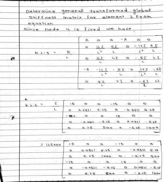
![Determine Jelation. the global mateix from [k][d] equivalent system from force we get . fare 15.05 6.25 0 -15 42 F29 15.05 6-](http://img.homeworklib.com/questions/96b83790-c347-11eb-a90e-afe2e9f19530.png?x-oss-process=image/resize,w_560) Please
upvote this if helpful
Please
upvote this if helpful
For the rigid frames shown in Figures P5-5 through P5-15, determine the displace- ments and rotations...
 For the rigid frames shown in Figures P5-5 through P5-15, determine the displace- ments and rotations of the nodes, the clement forces, and the reactions. The values of E. A, and I to be used are listed next to each figure. 25 kN/m In 4.5 m E= 210 GPa 450 1-8 x 10 m
problem 5-10 For the rigid frames shown in Figure, determine the displacements and rotations of the nodes the element forces, and the reactions. The values of E, A, and /to be used are listed next to...
 problem 5-10
For the rigid frames shown in Figure, determine the displacements and rotations of the nodes the element forces, and the reactions. The values of E, A, and /to be used are listed next to each figure. 10 KN E 210 GPa A x 10-2m 2 x 10-m O kN- m 10 kN Tm 5 kN m 45°
For the rigid frames shown in Figure, determine the displacements and rotations of the nodes the element forces, and the reactions....
problem 5-10
For the rigid frames shown in Figure, determine the displacements and rotations of the nodes the element forces, and the reactions. The values of E, A, and /to be used are listed next to each figure. 10 KN E 210 GPa A x 10-2m 2 x 10-m O kN- m 10 kN Tm 5 kN m 45°
For the rigid frames shown in Figure, determine the displacements and rotations of the nodes the element forces, and the reactions....
f(2x)=? f(?x)2= ? m(?)2 =? 5.14 For the rigid frame shown in Figure P5-14, determine the...
 f(2x)=? f(?x)2= ? m(?)2 =?
5.14 For the rigid frame shown in Figure P5-14, determine the displacements and rotations of the nodes, the element forces, and the reactions. Use the values of E, A, and I listed in the Figure. © 15 10 E = 30 x 10 Asin
f(2x)=? f(?x)2= ? m(?)2 =?
5.14 For the rigid frame shown in Figure P5-14, determine the displacements and rotations of the nodes, the element forces, and the reactions. Use the values of E, A, and I listed in the Figure. © 15 10 E = 30 x 10 Asin
For the rigid frame shown in figures, determine (1) the nodal displacements and rotations of the...
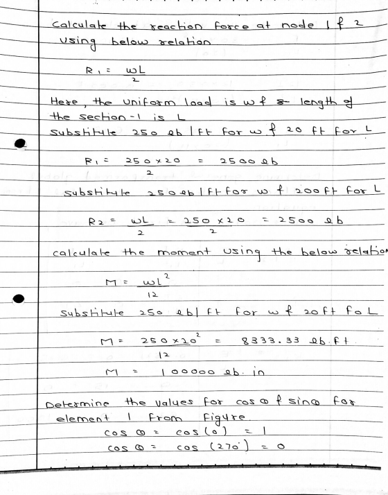
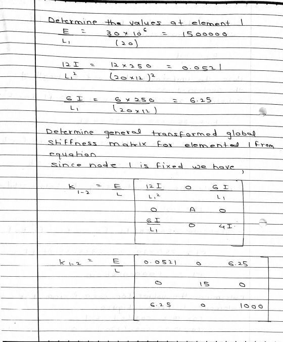
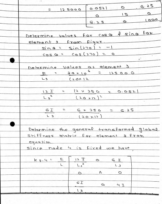
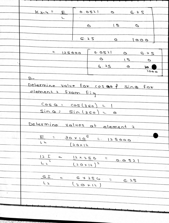
 For the rigid frame shown in figures, determine (1) the nodal displacements and rotations of the nodes, (2) the reactions, and (3) the forces in each element. 20 ft 5000 30x 10p A-10 in 200 in (for elements 1 2 and 3) 20 ft 0 1 in 4-2 in
Solve all problems using the finite element stiffness method. For the rigid frame shown in Figure P5-4, determine (1) the nodal displacements and rotation at node 4, (2) the reactions, and (3) the fo...
 Solve all problems using the finite element stiffness method. For the rigid frame shown in Figure P5-4, determine (1) the nodal displacements and rotation at node 4, (2) the reactions, and (3) the forces in each element. Then check equilibrium at node 4 Finally, draw the shear force and bending moment diagrams for each element. Let E 30x 103 ksi, A 8 in2, and I 800 in.4 for all elements. 20 kip 25 ft 25 ft 40 ft Figure P5-4...
Solve all problems using the finite element stiffness method. For the rigid frame shown in Figure...
 Solve all problems using the finite element stiffness method. For the rigid frame shown in Figure P5-4, determine (1) the nodal displacements and rotation at node 4, (2) the reactions, and (3) the forces in each element. Then check equilibrium at node 4. Finally, draw the shear force and bending moment diagrams for each element. LetE 30 x 103 ksi, A = 8 in,2 , and 1-800 in.4 for all elements. 20 kip 25 ft 25 ft- 40 ft 20...
For the beam shown in below, determine the displacements and rotations at the nodes, the forces in each element, and reactions. Also, draw the shear force and bending moment diagrams 10 kN 2 E210 GPa...
 For the beam shown in below, determine the displacements and rotations at the nodes, the forces in each element, and reactions. Also, draw the shear force and bending moment diagrams 10 kN 2 E210 GPa .20 kN m
For the beam shown in below, determine the displacements and rotations at the nodes, the forces in each element, and reactions. Also, draw the shear force and bending moment diagrams 10 kN 2 E210 GPa .20 kN m
For the beam shown in below, determine the displacements and rotations at the nodes, the forces in each element, and reactions. Also, draw the shear force and bending moment diagrams 10 kN 2 E210 GPa .20 kN m
2. For the spring assemblages shown in Figures 2a through 2e, determine the nodal displacements, the...
 2. For the spring assemblages shown in Figures 2a through 2e, determine the nodal displacements, the forces in each element, and the reactions. k = 3000 lb/in. k =3000 lb/in. k = 3000 lb/in. 2000 lb 1000 lb 4 Figure 2a. k= 500 lb/in. a 3000 lb/in. 2000 lb V 4 Rigid bar_ k =500 lb/in. Figure 2b.
MEE456 Homework Consider the beam shown below: 550 Analyze this beam using a 3-node, 2-element model...
 MEE456 Homework Consider the beam shown below: 550 Analyze this beam using a 3-node, 2-element model (hand calculations or E-200 G Pa and i=1 x 10" m'. Report on a summary page: a) Sketch a diagram of the beam showing the nodes, elements and loading (FE model). b) Present the displacements, rotations, reactions and, element forces and moments. c) Sketch a free body diagram of the beam showing the original loading and the reactions. d) Sketch a free body diagram...
Solve all problems using the finite element stiffness method. For the beams shown in Figure P4-...
 Solve all problems using the finite element stiffness method. For the beams shown in Figure P4- 21 determine the nodal displacements and slopes, the forces in each element, and the reactions. 2000 lb/ft E = 29 x 106 psi I = 200 in. - 15 ft 15 ft — Figure P4-21
 For the rigid frames shown in Figures P5-5 through P5-15, determine the displace- ments and rotations of the nodes, the clement forces, and the reactions. The values of E. A, and I to be used are listed next to each figure. 25 kN/m In 4.5 m E= 210 GPa 450 1-8 x 10 m
 problem 5-10
For the rigid frames shown in Figure, determine the displacements and rotations of the nodes the element forces, and the reactions. The values of E, A, and /to be used are listed next to each figure. 10 KN E 210 GPa A x 10-2m 2 x 10-m O kN- m 10 kN Tm 5 kN m 45°
For the rigid frames shown in Figure, determine the displacements and rotations of the nodes the element forces, and the reactions....
problem 5-10
For the rigid frames shown in Figure, determine the displacements and rotations of the nodes the element forces, and the reactions. The values of E, A, and /to be used are listed next to each figure. 10 KN E 210 GPa A x 10-2m 2 x 10-m O kN- m 10 kN Tm 5 kN m 45°
For the rigid frames shown in Figure, determine the displacements and rotations of the nodes the element forces, and the reactions....
 f(2x)=? f(?x)2= ? m(?)2 =?
5.14 For the rigid frame shown in Figure P5-14, determine the displacements and rotations of the nodes, the element forces, and the reactions. Use the values of E, A, and I listed in the Figure. © 15 10 E = 30 x 10 Asin
f(2x)=? f(?x)2= ? m(?)2 =?
5.14 For the rigid frame shown in Figure P5-14, determine the displacements and rotations of the nodes, the element forces, and the reactions. Use the values of E, A, and I listed in the Figure. © 15 10 E = 30 x 10 Asin
 For the rigid frame shown in figures, determine (1) the nodal displacements and rotations of the nodes, (2) the reactions, and (3) the forces in each element. 20 ft 5000 30x 10p A-10 in 200 in (for elements 1 2 and 3) 20 ft 0 1 in 4-2 in
 Solve all problems using the finite element stiffness method. For the rigid frame shown in Figure P5-4, determine (1) the nodal displacements and rotation at node 4, (2) the reactions, and (3) the forces in each element. Then check equilibrium at node 4 Finally, draw the shear force and bending moment diagrams for each element. Let E 30x 103 ksi, A 8 in2, and I 800 in.4 for all elements. 20 kip 25 ft 25 ft 40 ft Figure P5-4...
 Solve all problems using the finite element stiffness method. For the rigid frame shown in Figure P5-4, determine (1) the nodal displacements and rotation at node 4, (2) the reactions, and (3) the forces in each element. Then check equilibrium at node 4. Finally, draw the shear force and bending moment diagrams for each element. LetE 30 x 103 ksi, A = 8 in,2 , and 1-800 in.4 for all elements. 20 kip 25 ft 25 ft- 40 ft 20...
 For the beam shown in below, determine the displacements and rotations at the nodes, the forces in each element, and reactions. Also, draw the shear force and bending moment diagrams 10 kN 2 E210 GPa .20 kN m
For the beam shown in below, determine the displacements and rotations at the nodes, the forces in each element, and reactions. Also, draw the shear force and bending moment diagrams 10 kN 2 E210 GPa .20 kN m
For the beam shown in below, determine the displacements and rotations at the nodes, the forces in each element, and reactions. Also, draw the shear force and bending moment diagrams 10 kN 2 E210 GPa .20 kN m
 2. For the spring assemblages shown in Figures 2a through 2e, determine the nodal displacements, the forces in each element, and the reactions. k = 3000 lb/in. k =3000 lb/in. k = 3000 lb/in. 2000 lb 1000 lb 4 Figure 2a. k= 500 lb/in. a 3000 lb/in. 2000 lb V 4 Rigid bar_ k =500 lb/in. Figure 2b.
 MEE456 Homework Consider the beam shown below: 550 Analyze this beam using a 3-node, 2-element model (hand calculations or E-200 G Pa and i=1 x 10" m'. Report on a summary page: a) Sketch a diagram of the beam showing the nodes, elements and loading (FE model). b) Present the displacements, rotations, reactions and, element forces and moments. c) Sketch a free body diagram of the beam showing the original loading and the reactions. d) Sketch a free body diagram...
 Solve all problems using the finite element stiffness method. For the beams shown in Figure P4- 21 determine the nodal displacements and slopes, the forces in each element, and the reactions. 2000 lb/ft E = 29 x 106 psi I = 200 in. - 15 ft 15 ft — Figure P4-21
Most questions answered within 3 hours.
-
Write a program to solve the Josephus problem, with the following
modification:
Sample Input:
./a.out n...
asked 1 hour ago -
At the start of a CD it is spinning at a rate of 525 rpm
(revolutions...
asked 2 hours ago -
4. Without doing any calculations, predict whether the observed
∆T would increase, decrease or remain the...
asked 3 hours ago -
Based on the range, which of the following sets of scores has
the greatest variability? 3,...
asked 4 hours ago -
Ripples in a pond travel at a velocity of 3 m/s with one peak
passing a...
asked 4 hours ago -
A man stands on the roof of a building of height 13.0 mm and
throws a...
asked 4 hours ago -
The extent to which assets are financed by borrowed funds and
other liabilities is indicated by:...
asked 5 hours ago -
Explain in detail
Germany is the fifth largest economy
explain what goods and services Germany specializes...
asked 5 hours ago -
The density of platinum is 21.45 g/mL. If a cube of platinum
with a mass of...
asked 5 hours ago -
Accounts Receivable
Sales
A/R Posting
Extended Sales Invoice
Packing Slip
Compare invoice to packing slip 2...
asked 5 hours ago -
Michaella, age 23, is a full-time law student and is claimed by
her parents as a...
asked 5 hours ago -
Why are polymers not typically casted into products?
asked 6 hours ago