
Homework Answers


Add Answer to:
A rotating step shaft is loaded as shown, where the forces FA and FB are constant...
A rotating step shaft is loaded as shown, where the forces FA and FB are constant...
 A rotating step shaft is loaded as shown, where the forces FA and FB are constant at 600 lbf and 300 lbf, respectively, and the torque T alternates from 0 to 1800 lbf . in. The shaft is to be considered simply supported at points and C, and is made of AISI 1045 CD steel with a fully corrected endurance limit of Se = 40 kpsi. Let Kg = 2.1 and K = 1.7. For a design factor of 2.5...
A rotating step shaft is loaded as shown, where the forces FA and FB are constant...
 A rotating step shaft is loaded as shown, where the forces FA and FB are constant at 600 lbf and 300 lbf, respectively, and the torque T alternates from 0 to 1800 lbf in. The shaft is to be considered simply supported at points 0 and C, and is made of AISI 1045 CD steel with a fully corrected endurance limit of Se = 40 kpsi. Let Ki = 2.1 and K = 1.7. For a design factor of 2.5...
7 30.10 Required information A rotating step shaft is loaded as shown, where the forces FA...
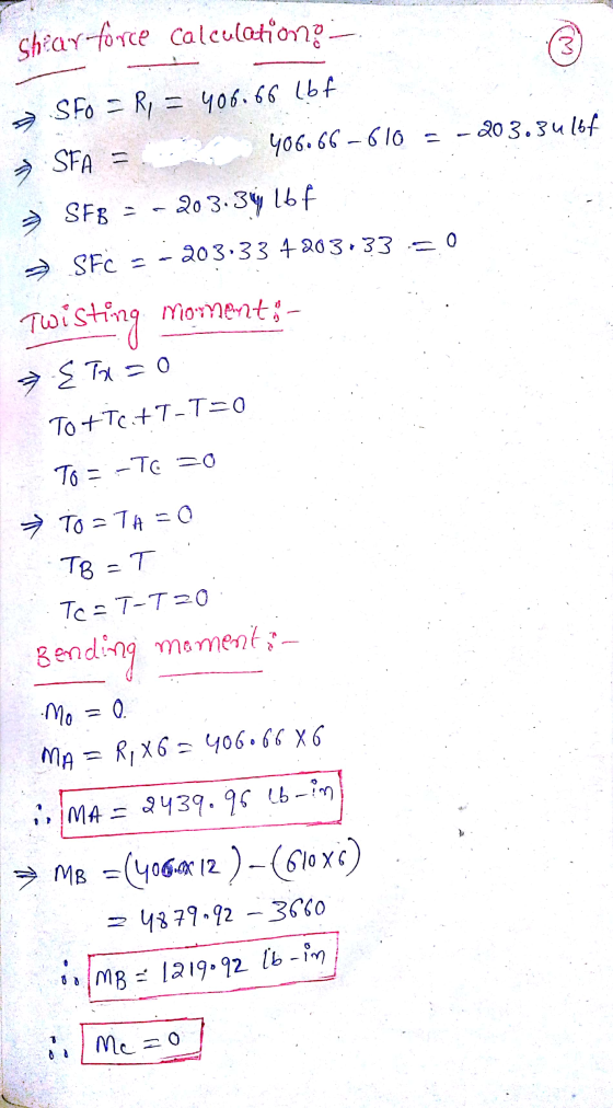
 7 30.10 Required information A rotating step shaft is loaded as shown, where the forces FA and Fg are constant ot 570 lbf and 285 lbf, respectively, and the torque alternates from 0 to 1800 lbf in. The shaft is to be considered simply supported at points and Cand is made of AISI 1045 CD steel with a fully corrected endurance limit of So" 40 kpsi. Let Kr 21 and Kis -17 Take the value of design factor to be...
-600 h 1. A rotating step shaft is loaded as shown, where the forces F. and...
 -600 h 1. A rotating step shaft is loaded as shown, where the forces F. and F: are constant at 600 lbf and 300 lbf, respectively, and the torque T alternates from 0 to 1800 Ibf in. The shaft is to be considered simply supported at points and C, and is made of AISI 1045 CD steel with a fully corrected endurance limit of Se = 40 kpsi. Let k, = 2.1 and K = 1.7. For a design factor...
A shaft is loaded in bending and torsion such that Ma- 73.7 N-m, Ta -48.8 Nm,...
 A shaft is loaded in bending and torsion such that Ma- 73.7 N-m, Ta -48.8 Nm, Mm = ? 7.5 N·m, Tm = 30.9 N. m. For the shaft, SU-630 MPa and Sy = 495 MPa, and a fully corrected endurance limit of Se -190 MPa is assumed. Let Kf - 2.13 and Kfs-1.89 Part 1 out of 2 With a design factor of 1.9, determine the minimum acceptable diameter of the shaft using the DE-Gerber criterion, the DE-elliptic criterion,...
A rotating shaft of 25-mm diameter is simply supported by bearing reaction forces R and R. The shaft is loaded with a transverse load of 13 kN as shown in the figure.
 A rotating shaft of 25-mm diameter is simply supported by bearing reaction forces R and R. The shaft is loaded with a transverse load of 13 kN as shown in the figure. The shaft is made from AISI 1045 hot-rolled steel. The surface has been machined. Determine (a) the minimum static factor of safety based on yielding. (b) the endurance limit, adjusted as necessary with Marin factors. (c) the minimum fatigue factor of safety based on achieving infinite life. (d) If the fatigue factor...
A 1-in, constant diameter shaft is loaded with forces at A and B as shown, with...
 A 1-in, constant diameter shaft is loaded with forces at A and B as shown, with ground reaction forces at O and C. The shaft also transmits a torque of 1500 lbf in throughout the length of the shaft. The shaft has a tensile yield strength of 130 kpsi. 460 lbf 575 lbf -12 in 18 in 1500 lbf-in А B ° To |--10 in- RO Rc Determine the minimum static factor of safety using the maximum-shear-stress failure theory, The...
augue application? 6-10 A rotating shaft of 25-mm diameter is simply supported by bearing reaction forces R and R2. The...
 augue application? 6-10 A rotating shaft of 25-mm diameter is simply supported by bearing reaction forces R and R2. The shaft is loaded with a transverse load of 13 kN as shown in the figure. The shaft is made from AISI 1045 hot-rolled steel. The surface has been machined. Determine (a) the minimum static factor of safety based on yielding. (b) the endurance limit, adjusted as necessary with Marin factors. (c) the minimum fatigue factor of safety based on achieving...
2. (8 points) A solid shaft shown below is loaded in bending and torsion with steady...
 2. (8 points) A solid shaft shown below is loaded in bending and torsion with steady rotation. The total bending moment and torque diagrams are also given. The selected shaft steel material has an ultimate tensile strength Sut = 68kpsi, initial yield stress Sy = 57kpsi, and fully corrected factors for endurance limit, kakykekakek, = 0.60. (a) (6 points) Determine the factor of safety at point D of the shaft using DE-ASME Elliptic criterion. Assume K, = 1.8 and Kfs...
1) [40 pts] Determination of minimum shaft diameter using DE-Gerber, DE-ASME Elliptic, DE-Soderberg, and DE-Goodman criteria...
 1) [40 pts] Determination of minimum shaft diameter using DE-Gerber, DE-ASME Elliptic, DE-Soderberg, and DE-Goodman criteria A shaft is loaded in bending and torsion such that M. = 66 Nm, T. = 42.496 Nm, Mm = 51.858 Nm, and Tm = 33 N m. For the shaft, S, = 700 MPa and S, = 560 MPa, and a fully corrected endurance limit of S, = 210 MPa is assumed. Let K = 2.2 and Kis = 1.8. With a design...
 A rotating step shaft is loaded as shown, where the forces FA and FB are constant at 600 lbf and 300 lbf, respectively, and the torque T alternates from 0 to 1800 lbf . in. The shaft is to be considered simply supported at points and C, and is made of AISI 1045 CD steel with a fully corrected endurance limit of Se = 40 kpsi. Let Kg = 2.1 and K = 1.7. For a design factor of 2.5...
 A rotating step shaft is loaded as shown, where the forces FA and FB are constant at 600 lbf and 300 lbf, respectively, and the torque T alternates from 0 to 1800 lbf in. The shaft is to be considered simply supported at points 0 and C, and is made of AISI 1045 CD steel with a fully corrected endurance limit of Se = 40 kpsi. Let Ki = 2.1 and K = 1.7. For a design factor of 2.5...
 7 30.10 Required information A rotating step shaft is loaded as shown, where the forces FA and Fg are constant ot 570 lbf and 285 lbf, respectively, and the torque alternates from 0 to 1800 lbf in. The shaft is to be considered simply supported at points and Cand is made of AISI 1045 CD steel with a fully corrected endurance limit of So" 40 kpsi. Let Kr 21 and Kis -17 Take the value of design factor to be...
 -600 h 1. A rotating step shaft is loaded as shown, where the forces F. and F: are constant at 600 lbf and 300 lbf, respectively, and the torque T alternates from 0 to 1800 Ibf in. The shaft is to be considered simply supported at points and C, and is made of AISI 1045 CD steel with a fully corrected endurance limit of Se = 40 kpsi. Let k, = 2.1 and K = 1.7. For a design factor...
 A shaft is loaded in bending and torsion such that Ma- 73.7 N-m, Ta -48.8 Nm, Mm = ? 7.5 N·m, Tm = 30.9 N. m. For the shaft, SU-630 MPa and Sy = 495 MPa, and a fully corrected endurance limit of Se -190 MPa is assumed. Let Kf - 2.13 and Kfs-1.89 Part 1 out of 2 With a design factor of 1.9, determine the minimum acceptable diameter of the shaft using the DE-Gerber criterion, the DE-elliptic criterion,...
 A 1-in, constant diameter shaft is loaded with forces at A and B as shown, with ground reaction forces at O and C. The shaft also transmits a torque of 1500 lbf in throughout the length of the shaft. The shaft has a tensile yield strength of 130 kpsi. 460 lbf 575 lbf -12 in 18 in 1500 lbf-in А B ° To |--10 in- RO Rc Determine the minimum static factor of safety using the maximum-shear-stress failure theory, The...
 augue application? 6-10 A rotating shaft of 25-mm diameter is simply supported by bearing reaction forces R and R2. The shaft is loaded with a transverse load of 13 kN as shown in the figure. The shaft is made from AISI 1045 hot-rolled steel. The surface has been machined. Determine (a) the minimum static factor of safety based on yielding. (b) the endurance limit, adjusted as necessary with Marin factors. (c) the minimum fatigue factor of safety based on achieving...
 2. (8 points) A solid shaft shown below is loaded in bending and torsion with steady rotation. The total bending moment and torque diagrams are also given. The selected shaft steel material has an ultimate tensile strength Sut = 68kpsi, initial yield stress Sy = 57kpsi, and fully corrected factors for endurance limit, kakykekakek, = 0.60. (a) (6 points) Determine the factor of safety at point D of the shaft using DE-ASME Elliptic criterion. Assume K, = 1.8 and Kfs...
 1) [40 pts] Determination of minimum shaft diameter using DE-Gerber, DE-ASME Elliptic, DE-Soderberg, and DE-Goodman criteria A shaft is loaded in bending and torsion such that M. = 66 Nm, T. = 42.496 Nm, Mm = 51.858 Nm, and Tm = 33 N m. For the shaft, S, = 700 MPa and S, = 560 MPa, and a fully corrected endurance limit of S, = 210 MPa is assumed. Let K = 2.2 and Kis = 1.8. With a design...
Most questions answered within 3 hours.
-
I wish to estimate µ, the mean of a population. After I collect
and an-
alyze...
asked 4 minutes ago -
You are interested in whether students that have a male
instructors perform differently on exams. To...
asked 10 minutes ago -
Discuss the following: The policies that promote economic
growth. Why are some countries more developed than...
asked 6 minutes ago -
I am supposed to reduce redundancy in the code and also make
unknown inputs, output "unknown"....
asked 12 minutes ago -
The ages of a group of
147
randomly selected adult females have a standard deviation of...
asked 16 minutes ago -
Blood alcohol content (BAC) is a measure of how much alcohol is
in someone’s blood. It...
asked 23 minutes ago -
A flow rate of 0.4 m / s of air enters a compressor at 100 kPa....
asked 51 minutes ago -
Write a balanced chemical equation for the reaction between HCl
and NaOH. Be sure to include...
asked 56 minutes ago -
A 200 g mass is gently hung on a vertical spring which stretches
it 20cm before...
asked 58 minutes ago -
Elaborate on some of the difficulties in determine the value of
information, as well as the...
asked 55 minutes ago -
A person wants to use a lever to lift a dumpster weighing 4700
N. The lever...
asked 1 hour ago -
Hello,
Can you assist with the 2 part multiple choice question?
1A) Which of the following...
asked 1 hour ago