CALCULATE THE SUPPORT REACTION , DRAW FREE BODY DIAGRAM FOR EACH
JOINT AND STATE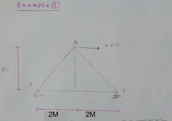
Homework Answers


Add Answer to:
CALCULATE THE SUPPORT REACTION , DRAW FREE BODY DIAGRAM FOR EACH
JOINT AND STATE
Example 2...
CALCULATE THE SUPPORT REACTION , DRAW FREE BODY DIAGRAM FOR EACH JOINT AND STATE YOUR RESUALT...
 CALCULATE THE SUPPORT REACTION , DRAW FREE BODY DIAGRAM FOR EACH
JOINT AND STATE YOUR RESUALT
ExamPLE 1 B 3KN zm 45° A n 2m
CALCULATE THE SUPPORT REACTION , DRAW FREE BODY DIAGRAM FOR EACH
JOINT AND STATE YOUR RESUALT
ExamPLE 1 B 3KN zm 45° A n 2m
Draw a free body diagram. 5 kN 6 kN 8 kN 2m- 2 m Prob. 5-15
 Draw a free body
diagram.
5 kN 6 kN 8 kN 2m- 2 m Prob. 5-15
Draw a free body
diagram.
5 kN 6 kN 8 kN 2m- 2 m Prob. 5-15
(a) Draw the free-body diagram for the steel beam with applied and reaction forces. [4 marks]...
 (a) Draw the free-body diagram for the steel beam with applied and reaction forces. [4 marks] (b) Determine the reaction forces on the beam caused by the pin and tension of the cable. [11 marks] The pulley is a frictionless pulley and at C hangs a 60 kg cylinder. Neglect the weight of the beam. D ВА с 5 m 5m - 3m
Please draw the forces acting on the free body diagram if necessary and answer the question...
 Please draw the forces acting on
the free body diagram if necessary and answer the question clearly.
Thank you.
Angular Momentum Two small objects of mass 2M, and 3M are attached to a rod of mass M and length '4a' as shown in the figure. If the system is rotated with angular velocity o about the axis AB shown, find the angular momentum of the system. Find Isys L = Isys W 3M 2M
Please draw the forces acting on
the free body diagram if necessary and answer the question clearly.
Thank you.
Angular Momentum Two small objects of mass 2M, and 3M are attached to a rod of mass M and length '4a' as shown in the figure. If the system is rotated with angular velocity o about the axis AB shown, find the angular momentum of the system. Find Isys L = Isys W 3M 2M
a. Draw a free-body diagram for the beam shown above and derive expressions for the support...
 a. Draw a free-body diagram for the beam shown above and derive
expressions for the support reactions at A and B
b. Draw internal force (shear and bending moment) diagrams.
c. If a = 10 ft and M0 = 200 ft-lb, use the dimensions of the
beam cross-section, provided on the previous page, to compute the
maximum flexural and shear stresses on the beam cross-section.
d. If the allowable bending stress is 925 psi and the allowable
shear stress is...
a. Draw a free-body diagram for the beam shown above and derive
expressions for the support reactions at A and B
b. Draw internal force (shear and bending moment) diagrams.
c. If a = 10 ft and M0 = 200 ft-lb, use the dimensions of the
beam cross-section, provided on the previous page, to compute the
maximum flexural and shear stresses on the beam cross-section.
d. If the allowable bending stress is 925 psi and the allowable
shear stress is...
Please show all steps, sketch free-body diagram, and state assumptions. Create a drawing of the designed cotter joint. A...
 Please show all steps, sketch free-body diagram, and
state assumptions.
Create a drawing of the designed cotter joint. Assume
non-critical dimensions.
Design stresses are 55 MPa in tension; 40 MPa in shear and 70 MPa in crushing. Draw a neat sketch of the joint designed joint to connect two mild steel rods for a pull of 30 kN. The maximum permissible 1 a cotter [Ans. d 22 mm; d,=32 mm ; t= 14 mm ; d, =44 mm ; b=30...
Please show all steps, sketch free-body diagram, and
state assumptions.
Create a drawing of the designed cotter joint. Assume
non-critical dimensions.
Design stresses are 55 MPa in tension; 40 MPa in shear and 70 MPa in crushing. Draw a neat sketch of the joint designed joint to connect two mild steel rods for a pull of 30 kN. The maximum permissible 1 a cotter [Ans. d 22 mm; d,=32 mm ; t= 14 mm ; d, =44 mm ; b=30...
a. Draw a complete free-body diagram for the beam shown in Fig. 1. Must show and...
 a. Draw a complete free-body diagram for the beam shown in Fig.
1. Must show and label x-y coordinate system, support reactions,
loads, and dimensions
b. Derive formulas for all support reactions using conditions of
equilibrium. Must show all work.
c. Using the student variables shown below, calculate beam
support reactions and draw shear and bending moment diagrams. To
receive full credit, support reactions and loads must be shown on a
free-body diagram. Each shear and bending moment diagram must...
a. Draw a complete free-body diagram for the beam shown in Fig.
1. Must show and label x-y coordinate system, support reactions,
loads, and dimensions
b. Derive formulas for all support reactions using conditions of
equilibrium. Must show all work.
c. Using the student variables shown below, calculate beam
support reactions and draw shear and bending moment diagrams. To
receive full credit, support reactions and loads must be shown on a
free-body diagram. Each shear and bending moment diagram must...
Date: Draw free body diagram and write equilibrium equation needed for determining the reaction force at...
 Date: Draw free body diagram and write equilibrium equation needed for determining the reaction force at the point B. A is a hinge support and B is a roller support. C is the rigió connection between two members. (25 I. points) 10 5 10
Determine the tension in the cable and reaction forces at A. (A) Draw the free-body diagram...
 Determine the tension in the cable and reaction forces at A.
(A) Draw the free-body diagram of the beam. (B) Determine the tension in the cable and the reaction forces at A 30° 30 in 800 1b 30 in 4-30 in
Determine the tension in the cable and reaction forces at A.
(A) Draw the free-body diagram of the beam. (B) Determine the tension in the cable and the reaction forces at A 30° 30 in 800 1b 30 in 4-30 in
Reactions of all pins and members must be calculated. Draw the free-body diagram of each member...
 Reactions of all pins and members must be calculated.
Draw the free-body diagram of each member (AB, BC, AD, EDC) and pin (A, B, C, D, E). Then, find all the forces previously reported. Force at C (5 kN) is applied on the pin C 5 kN/m 1 kN/m 1 kN/m 2 kN-m 2 m 1.5 m 1.5 m 5 kN
Reactions of all pins and members must be calculated.
Draw the free-body diagram of each member (AB, BC, AD, EDC) and pin (A, B, C, D, E). Then, find all the forces previously reported. Force at C (5 kN) is applied on the pin C 5 kN/m 1 kN/m 1 kN/m 2 kN-m 2 m 1.5 m 1.5 m 5 kN
 CALCULATE THE SUPPORT REACTION , DRAW FREE BODY DIAGRAM FOR EACH
JOINT AND STATE YOUR RESUALT
ExamPLE 1 B 3KN zm 45° A n 2m
CALCULATE THE SUPPORT REACTION , DRAW FREE BODY DIAGRAM FOR EACH
JOINT AND STATE YOUR RESUALT
ExamPLE 1 B 3KN zm 45° A n 2m
 Draw a free body
diagram.
5 kN 6 kN 8 kN 2m- 2 m Prob. 5-15
Draw a free body
diagram.
5 kN 6 kN 8 kN 2m- 2 m Prob. 5-15
 (a) Draw the free-body diagram for the steel beam with applied and reaction forces. [4 marks] (b) Determine the reaction forces on the beam caused by the pin and tension of the cable. [11 marks] The pulley is a frictionless pulley and at C hangs a 60 kg cylinder. Neglect the weight of the beam. D ВА с 5 m 5m - 3m
 Please draw the forces acting on
the free body diagram if necessary and answer the question clearly.
Thank you.
Angular Momentum Two small objects of mass 2M, and 3M are attached to a rod of mass M and length '4a' as shown in the figure. If the system is rotated with angular velocity o about the axis AB shown, find the angular momentum of the system. Find Isys L = Isys W 3M 2M
Please draw the forces acting on
the free body diagram if necessary and answer the question clearly.
Thank you.
Angular Momentum Two small objects of mass 2M, and 3M are attached to a rod of mass M and length '4a' as shown in the figure. If the system is rotated with angular velocity o about the axis AB shown, find the angular momentum of the system. Find Isys L = Isys W 3M 2M
 a. Draw a free-body diagram for the beam shown above and derive
expressions for the support reactions at A and B
b. Draw internal force (shear and bending moment) diagrams.
c. If a = 10 ft and M0 = 200 ft-lb, use the dimensions of the
beam cross-section, provided on the previous page, to compute the
maximum flexural and shear stresses on the beam cross-section.
d. If the allowable bending stress is 925 psi and the allowable
shear stress is...
a. Draw a free-body diagram for the beam shown above and derive
expressions for the support reactions at A and B
b. Draw internal force (shear and bending moment) diagrams.
c. If a = 10 ft and M0 = 200 ft-lb, use the dimensions of the
beam cross-section, provided on the previous page, to compute the
maximum flexural and shear stresses on the beam cross-section.
d. If the allowable bending stress is 925 psi and the allowable
shear stress is...
 Please show all steps, sketch free-body diagram, and
state assumptions.
Create a drawing of the designed cotter joint. Assume
non-critical dimensions.
Design stresses are 55 MPa in tension; 40 MPa in shear and 70 MPa in crushing. Draw a neat sketch of the joint designed joint to connect two mild steel rods for a pull of 30 kN. The maximum permissible 1 a cotter [Ans. d 22 mm; d,=32 mm ; t= 14 mm ; d, =44 mm ; b=30...
Please show all steps, sketch free-body diagram, and
state assumptions.
Create a drawing of the designed cotter joint. Assume
non-critical dimensions.
Design stresses are 55 MPa in tension; 40 MPa in shear and 70 MPa in crushing. Draw a neat sketch of the joint designed joint to connect two mild steel rods for a pull of 30 kN. The maximum permissible 1 a cotter [Ans. d 22 mm; d,=32 mm ; t= 14 mm ; d, =44 mm ; b=30...
 a. Draw a complete free-body diagram for the beam shown in Fig.
1. Must show and label x-y coordinate system, support reactions,
loads, and dimensions
b. Derive formulas for all support reactions using conditions of
equilibrium. Must show all work.
c. Using the student variables shown below, calculate beam
support reactions and draw shear and bending moment diagrams. To
receive full credit, support reactions and loads must be shown on a
free-body diagram. Each shear and bending moment diagram must...
a. Draw a complete free-body diagram for the beam shown in Fig.
1. Must show and label x-y coordinate system, support reactions,
loads, and dimensions
b. Derive formulas for all support reactions using conditions of
equilibrium. Must show all work.
c. Using the student variables shown below, calculate beam
support reactions and draw shear and bending moment diagrams. To
receive full credit, support reactions and loads must be shown on a
free-body diagram. Each shear and bending moment diagram must...
 Date: Draw free body diagram and write equilibrium equation needed for determining the reaction force at the point B. A is a hinge support and B is a roller support. C is the rigió connection between two members. (25 I. points) 10 5 10
 Determine the tension in the cable and reaction forces at A.
(A) Draw the free-body diagram of the beam. (B) Determine the tension in the cable and the reaction forces at A 30° 30 in 800 1b 30 in 4-30 in
Determine the tension in the cable and reaction forces at A.
(A) Draw the free-body diagram of the beam. (B) Determine the tension in the cable and the reaction forces at A 30° 30 in 800 1b 30 in 4-30 in
 Reactions of all pins and members must be calculated.
Draw the free-body diagram of each member (AB, BC, AD, EDC) and pin (A, B, C, D, E). Then, find all the forces previously reported. Force at C (5 kN) is applied on the pin C 5 kN/m 1 kN/m 1 kN/m 2 kN-m 2 m 1.5 m 1.5 m 5 kN
Reactions of all pins and members must be calculated.
Draw the free-body diagram of each member (AB, BC, AD, EDC) and pin (A, B, C, D, E). Then, find all the forces previously reported. Force at C (5 kN) is applied on the pin C 5 kN/m 1 kN/m 1 kN/m 2 kN-m 2 m 1.5 m 1.5 m 5 kN
Most questions answered within 3 hours.
-
Why are polymers not typically casted into products?
asked 49 seconds ago -
When rolling a die 129 times, what is the probability of rolling
a 6 no more...
asked 17 minutes ago -
4. A call option currently sells for $7.75. It has a strike
price of $85 and...
asked 6 minutes ago -
1.
You need to prepare 10.0 liters of an acid aqueous solution with a
pH of...
asked 9 minutes ago -
Along an aggregate supply curve, if the level of output is less
than the natural level...
asked 9 minutes ago -
By 2025, annual consumption in emerging markets will total $30
trillion and contribute more than ________...
asked 14 minutes ago -
At what point does reformation cease to be a viable option for
those who are oppressed...
asked 18 minutes ago -
Place letters corresponding to amounts in the proper order for
lightest to heaviest samples:
a) 2100...
asked 22 minutes ago -
Consider the multicore processor with 6 heterogeneous cores
labelled C1, C2, C3, C4, C5, and C6....
asked 25 minutes ago -
Document system components according to standards and procedures
(Implement and hand over system components) IT administrative
asked 25 minutes ago -
The college asked 700 students if they wanted a longer spring
break and 600 students said...
asked 25 minutes ago -
Determine the temperature (in Celsius) at which 1.00 mole of an
ideal gas will have a...
asked 49 minutes ago